


Operator’s Guide 173
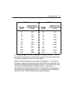
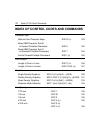
10 Pitch 12 Pitch
Maximum Dot Maximum Dot
Density Columns Per Line Density Columns Per Line
(d1d2) (c1c2) (d1d2) (c1c2)
50 680 60 816
60 816 72 979
75 1020 90 1224
100 1360 120 1632
120 1632 144 1958
150 2040 180 2448
200 2720 240 3264
240 3264 288 3917
300 4080 360 4896
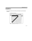
g1 through gx specify the pin fire patterns for each dot column. The x in
gx refers to the maximum number of dot columns that can be reserved for
the specified graphics density, as shown above.
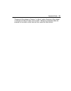
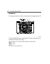
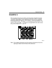
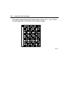
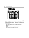
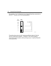
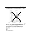
Eight of the 9 printhead pins are used to print graphics. To calculate g1
through gx, design each dot column as a cell that is 8-dot-rows high, then
add the cell values vertically for each dot column. The value of g for each
column can be expressed as a decimal number: the bits set to 1
correspond to the printhead pins that fire to create dots in each pattern. If
a bit is set, the corresponding pin fires. If it is not set, the corresponding
pin does not fire. See the figure and example that follow.