


Operator's Guide B-11
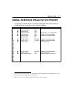
CONNECTION EXAMPLES
Use the following examples as guides in building a serial interface cable.
The following examples are presented:
•
IBM PC to Printer
•
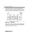
IBM PC/AT to Printer
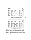
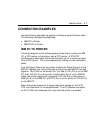
IBM PC TO PRINTER
The wiring diagram on the following page shows how to connect an IBM
PC, a DTE device, to the printer, also a DTE device. A DTE/DTE
interface must make each side of the link seem as if it is receiving inputs
from a DCE device. This is accomplished by making a cross-connected
cable.
First, the Signal Ground on the printer is tied to the Signal Ground on the
IBM PC; likewise, the Frame Grounds on the printer and IBM PC are tied
together. Next, RxD on the printer (Pin 3) is tied to TxD (Pin 2) on the IBM
PC; then TxD (Pin 2) on the printer is tied to RxD (Pin 3) on the IBM PC.
Lastly, the control signals are connected: DTR (Pin 20) on the printer to
DSR (Pin 6) on the IBM PC, and RTS (Pin 4) on the printer to CTS (Pin 5)
on the IBM PC.
When the printer powers up, it always raises the voltage on its Pin 20,
DTR, and maintains it in an elevated state. The PC receives this signal
on Pin 6, DSR, and interprets it to mean that the printer is available.