


Operator's Guide B-7
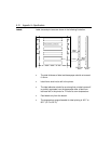
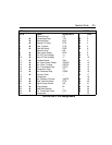
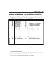
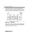
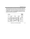
SERIAL INTERFACE PIN-OUTS FOR PRINTER
The printer is a DTE device. The table that follows summarizes the pin
assignments on the printer end of a serial interface.
Pin # Signal Name Abbr. Comment
1 Frame Ground FG
2
%
Transmitted Data TxD
3
&
Received Data RxD
4
%
Request To Send RTS Always high; + 12v, signal level.
5
&
Clear To Send CTS <optional, not implemented>
6
&
Data Set Ready DSR <optional, not implemented>
7 Signal Ground SG
8
9
%
RS-422-A TxD- TxD 422- <optional, not implemented>
10
%
RS-422-A TxD+ TxD 422+ <optional, not implemented>
11
%
Auxiliary DTR
*
—— Same as Pin 20.
12
13
14
15
16
17
18
&
RS-422-A RxD+
**
RxD 422+ <optional, not implemented>
19
%
Auxiliary DTR
*
—— Same as Pin 20.
20
%
Data Terminal Ready DTR High until buffer fills, then low.
21
22
23
24
25
*
Technically, not an RS-232-C signal. See ”DTR Polarity” under Serial Options in the configuration menu. See
“Handshaking” later in this appendix for more information.
**
RxD on Pin 3 is used as the differential complement RxD 422- of this signal line.