


B-4 Appendix B—Serial Interface
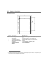
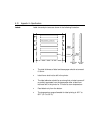
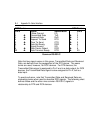
DTE Device DCE Device
Pin # Signal Abbreviation Pin #
1 Frame Ground FG 1
2
%
Transmitted Data TxD
%
2
3
&
Received Data RxD
&
3
4
%
Request To Send RTS
%
4
5
&
Clear To Send CTS
&
5
6
&
Data Set Ready DSR
&
6
7 Signal Ground SG 7
8
&
Data Carrier Detect DCD
&
8
20
%
Data Terminal Ready DTR
%
20
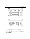
Common RS-232-C
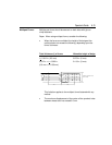
Note that two signal names in this group, Transmitted Data and Received
Data, are defined from the perspective of the DTE device. The same
terms are used, however, for DCE devices. For DTE devices, the
Transmitted Data signal is assigned to Pin 2 and is a data output; for DCE
devices, the Transmitted Data signal is also assigned to Pin 2, but is a
data input.
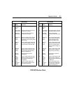
To avoid confusion, note that Transmitted Data and Received Data are
misleading terms when used to describe DCE signals. The following chart
defines these and the other nine common RS-232-C signals in
relationship to DTE and DCE devices.