


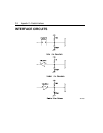

C-4 Appendix C—Parallel Interface
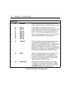
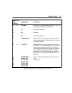
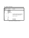
Signal Pin #
and Direction Signal Name Description
1
&
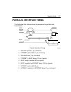
STROBE*
Synchronous input signal for strobing data into the
printer. Normally high. Pulse width minimum is 1 ms.
2
&
DATA 1
These 8 signals represent the 8-bit data byte.
3
&
4
&
5
&
6
&
7
&
8
&
9
&
DATA 2
DATA 3
DATA 4
DATA 5
DATA 6
DATA 7
DATA 8
All eight bits of each character are transmitted to the
printer simultaneously. A high level represents a
binary "1" digit; a low level represents a binary "0"
digit. Data pulse width minimum is 3 ms. Data lines
must be asserted before the strobe goes low.
10
%
ACKNLG*
The printer sends this pulse to the computer after
each character is received. ACKNLG* may be
referred to as a "data request pulse," indicating that
data were received, and the printer is ready to
accept more. ACKNLG* is set high until it receives a
character, then goes low with a pulse width of 5 ms.
This signal works together with the BUSY signal.
11
%
BUSY
When high, data transfer from the computer to the
printer is prevented. BUSY is set high when a
character is strobed into the parallel port, and set
low when a byte has been read. This signal works
together with the ACKNLG* signal.
12
%
PAPER OUT
A high signal indicates the printer is out of paper.
The signal comes directly from the printer's paper
out switch through a buffer. The buffer also drives
the
PAPER
indicator on the switch panel.
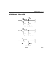
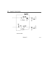
Parallel Interface Pin Assignments