


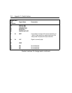

C-2 Appendix C—Parallel Interface
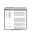
DATA
The host computer sends each data byte to the printer in parallel across
Data Lines 1 through 8 (connector Pins 2 through 9). A bit set to logical
"1" is transmitted as a high signal; a bit set to logical "0" is transmitted as
a low signal.
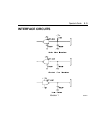
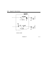
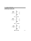
Input data and all interface control signals are compatible with TTL
(Transistor-Transistor Logic) levels, 0 to +5 volts.
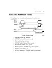
SYNCHRONIZATION
Synchronization is accomplished by externally supplied STROBE* pulses.
The port receives data prior to the leading (negative) edge of STROBE*.
HANDSHAKING
Handshaking is accomplished by ACKNLG* (acknowledge) and BUSY
signals. These signals control data flow across the parallel interface.
The computer monitors the state of BUSY to determine if the printer is
ready to accept a character. If BUSY is not asserted, the computer sends
a character to the interface on DATA 1 through DATA 8.
After the data setup time, the computer asserts STROBE*. As each
character is received, the leading (negative) edge of STROBE* clocks the
BUSY flipflop, which resets it. This asserts the BUSY signal and latches
the received character into the parallel port register.
When the printer has processed the character and is ready for another, it
sets the BUSY flipflop. This negates the BUSY signal and produces a 5
m
s ACKNLG* pulse. The interface is ready to accept another character as
soon as the ACKNLG* pulse begins.
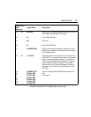
*
The asterisks following a signal name signifies that logic 1 is an active low.