


RESTRICTED USE ONLY Fargo Electronics, Inc.
HDP5000 High Definition Card Printer/Encoder User Guide (Rev. 1.4)
4-7
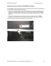
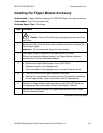
Installing the Lamination Module Accessory
Parts included: Lamination Module Accessory Kit, PCB-INTF Board, Torx Tool and screws
Tools needed: Torx Tool (included in kit)
Estimated Repair Time: 10 minutes
Step Procedure
1
Caution: Power off the Printer by unplugging the power cord from
the Printer.
2 Remove the USB, Serial, Ethernet communication connections.
Important: Do not remove the Covers for this procedure.
3 The Lamination Module is installed at the output side of the Flipper Module.
OR
If there is no Flipper Module, it is installed at the output side of the Printer.
Remove the Card Output Hopper.
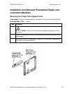
4 a. Remove the Output Side Upgrade Cover (D910139-01).
b. Release the latch on the Upgrade Cover.
c. Pull on the bottom of the Upgrade Cover to remove it from the printer.
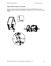
5 a. Turn the Printer and the Flipper Module on their back.
b. Use the Torx tool provided to remove the two (2) screws from the bottom
of the Flipper Module. Save the screws for later for reattachment.
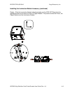
6 Slide the Lamination Module attachment tabs and the PCB-INTF Board into
the appropriate slots at the base of Printer or Flipper Module.
7 Use the two (2) screws provided to attach the Lamination Module to the
Printer. See Display A on the next page.
Continued on the next page