


2
2-2
TCP/IP Ethernet Communications User’s Manual - August 1997 GFK-1084B
CMM 321
ETHERNET
INTERFACE
OK
LAN
SER
STAT
SER
a45481c
OK
LAN
RESTART
SOFTWARE
PORT
STAT
SERIAL
NUMBER
LABEL
TRANSCEIVER
PORT
STATION
MANAGER
PORT
STATION
ADDRESS
LABEL
LOADER
(PORT 1)
(PORT 2)
AAUI
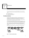
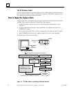
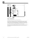
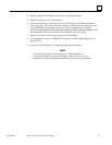
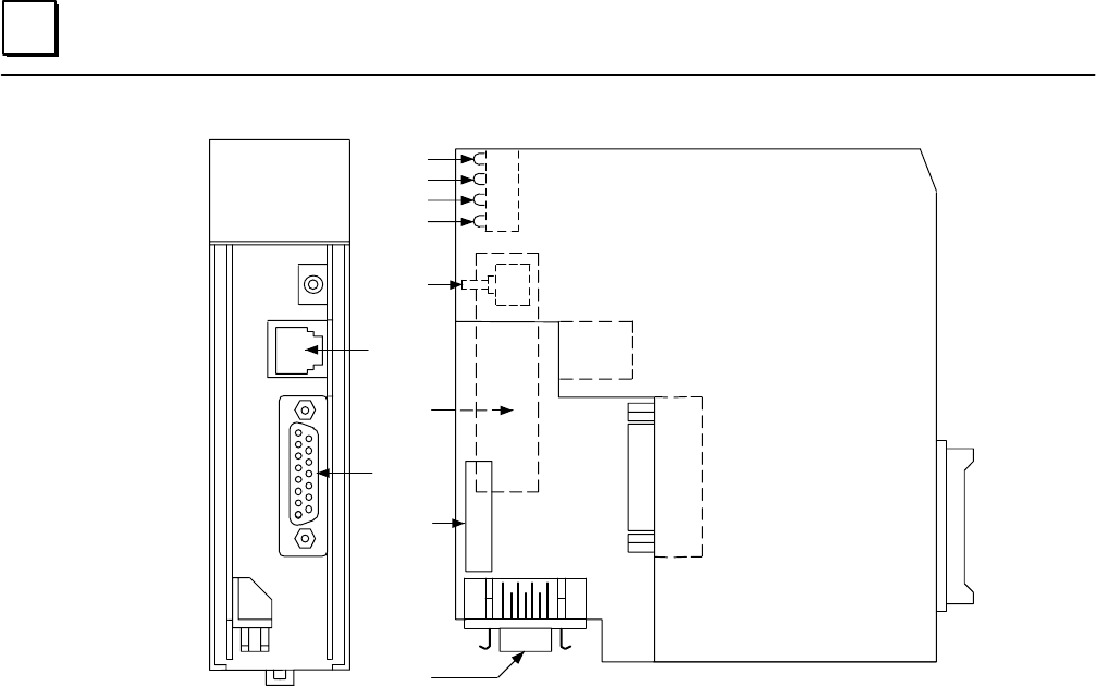
Figure 2-1. Ethernet Interface
The Ethernet Interface has several user-accessible elements.
Four LEDs are located at the top of the board. The Restart button is located immediately
below the LEDs. The RS-232 serial port with the RJ-11 connector (similar to a modular
telephone connector) is the Station Manager port. The RS-485 serial port with the 15-pin
“D” connector located below the Station Manager port is the module’s Software Loader
port. The 14-pin AAUI connector, facing downward, is the Transceiver port.
The Restart button, Station Manager port, Software Loader port, MAC address label, and
serial number label are normally concealed by the front cover. Remove the front cover
to access them.