


B
B-6
TCP/IP Ethernet Communications User’s Manual - August 1997 GFK-1084B
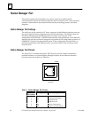
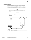
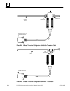
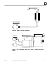
The AAUI Port for the Ethernet Interface
The Ethernet Interface is equipped with an Apple Attachment Unit Interface (AAUI) port
for connecting to the network. Compatible transceivers can be purchased that support
10Base5 and 10Base2 coaxial cables as well as twisted pair and fiber optic cables. The
AAUI standard makes your selection of transceiver and trunk cable medium transparent
to the Ethernet Interface.
Your network cables must meet the applicable 802.3 standards.
This section presents the information you need to specify the cables and related
components required for Ethernet Communications. Information in this section
includes AAUI port pinouts and AAUI cable diagrams.
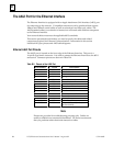
Ethernet AAUI Port Pinouts
The AAUI port is located on the front edge of the Ethernet Interface. This port is a
14-pin D-type female connector. It is used to connect the Ethernet Interface to the 802.3
transceiver. Connector pinouts are shown in Table B-4.
Table B-5. Pinouts of the AAUI Port
Pin Number Signal Description
1 FN Pwr +5V @ 1.9W
2 DI-A Data In circuit A
3 DI-B Data In circuit B
4 Vc Voltage common
5 CI-A Control In circuit A
6 CI-B Control In circuit B
7 +5V +5V from host
8 +5V Secondary +5V from host
9 DO-A Data Out circuit A
10 DO-B Data Out circuit B
11 Vc Secondary Voltage Common
12 -nc- Reserved
13 -nc- Reserved
14 FN Pwr Secondary +5V
SHELL PG Protective Ground (Conductive
shell and shield)
Note
Pinouts are provided for troubleshooting purposes only. Cables are
readily available from commercial distributors. GE Fanuc recommends
that you purchase rather than make transceiver cables.