


3
3-45
GFK-1084B Chapter 3 Programming Communications Requests
Monitoring the Communications Channel
Once you have a working ladder program, you can use the status data to monitor your
communications activity and take the desired action upon certain events. The primary
indicators of a communications channel are the Channel Status bits: Channel Error bit
and Data Transfer bit. In addition, the CRS word and the DCS words can be used to
more precisely troubleshoot any problems that may occur.
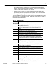
Monitoring the COMMREQ Status Word
It is critical to monitor the CRS word for each COMMREQ function you initiate. First,
zero the associated CRS word before executing the COMMREQ function. Then when
the CRS word becomes non-zero, you know the Ethernet Interface has updated it. If the
CRS word is updated to a one (1), then the Command Block was processed successfully
by the Ethernet Interface. If the CRS word is updated to a value other than 1, then an
error has occurred in processing the Command Block. See Section 4 of this chapter for
CRS word error codes.
Do not use data received from a server until the CRS word for that channel is 1 or the
Data Transfer bit goes to 1.
Monitoring the Channel Error Bit
This bit (normally 0) is the primary indicator for an error on a channel. It indicates any
channel error, fatal or non-fatal. It does not necessarily indicate that the channel is down
(idle). You may want to monitor this bit and simply reinitiate the Read or Write
command if the bit indicates an error. Or you may want to execute the Retrieve Detailed
Channel Status Command to find out if the channel is down and possibly why it went
down. Keep in mind, however, that the status code may change from between the time
the Channel Error bit indicates an error and the time the Retrieve Detailed Channel
Status Command retrieves the code.
The Channel Error bit for a channel is not meaningful until after the Ethernet Interface
updates the CRS word confirming the Read or Write command for that channel. In the
case of an Establish Channel command, the CRS word is updated before the Channel
Error bit is set to 1.
Monitoring the Data Transfer Bit
Typically you will set up a channel to perform repetitive reads or writes. The Data
Transfer bit pulses ( 0 → 1 → 0) each time there is a successful read or write. This can be
an indicator to the ladder program to move the most recent data to another location.
The Data Transfer bit for a channel is not meaningful until after the Ethernet Interface
updates the CRS word confirming the Read or Write command for that channel.
Do not use data received from a server until the CRS word confirming the Read
command for that channel is 1 or the Data Transfer bit goes to 1. Do not assume that when
the Data Transfer bit goes to 1 that a transfer has just completed during the last scan. The Data
Transfer bit is not closely synchronized in time with the transfer. The bit only indicates
that a transfer has occurred in a past scan. A rising edge on the Data Transfer bit
indicating that a transfer has completed successfully does not guarantee that the next
transfer has not begun or completed.