


3
3-13
GFK-1084B Chapter 3 Programming Communications Requests
When the read period is very long (minutes or hours). In this case a shorter timeout
value can be specified so the application doesn’t have to wait for the read period to
expire before taking action.
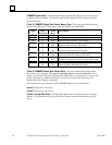
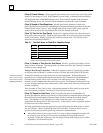
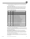
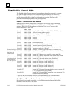
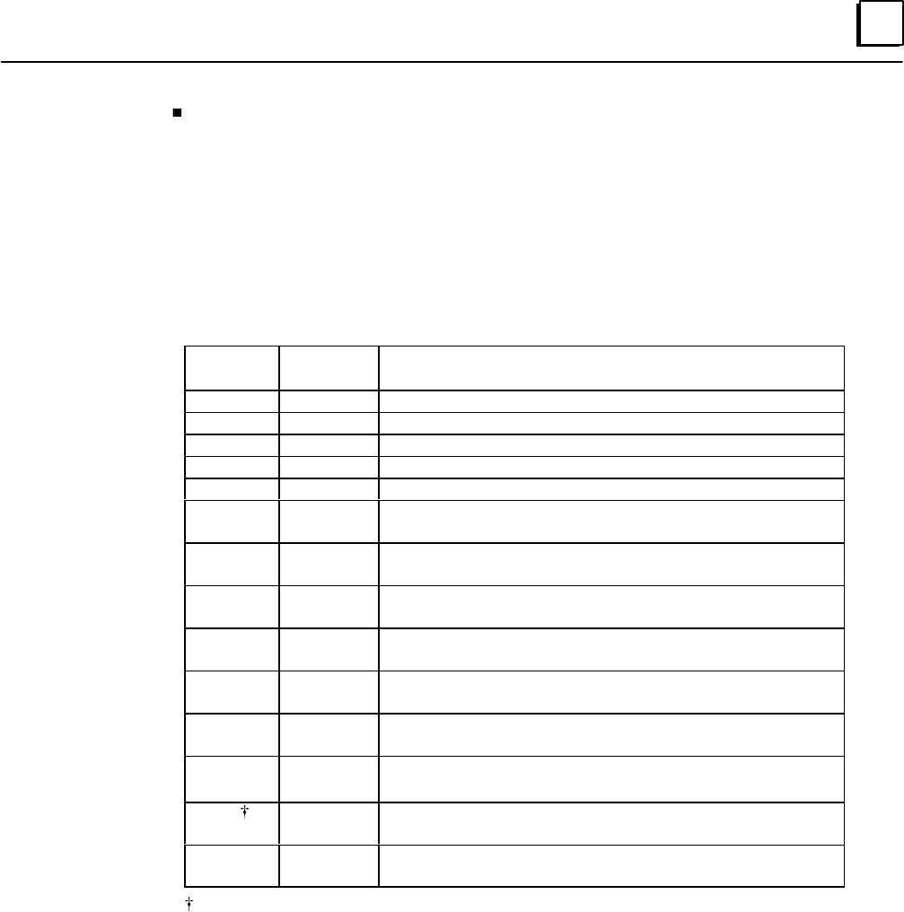
(Word 13) Local PLC - Memory Type: Words 13-14 specify the location in the local PLC
where the Ethernet Interface will store data received from the remote PLC. The size of
this area is set by the size of the data read from the remote PLC (Word 17). The user is
responsible for assuring that this area is large enough to contain the requested data
without overwriting other application data. Valid memory types are listed in Table 3-2.
Table 3-2. Series 90 PLC Memory Types
Type
Value
(Decimal) Description
%L* 0 Program Block Local register memory (word mode)
%P* 4 Program register memor y (word mode)
%R 8 Register memory (word mode)
%AI 10 Analog input memory (word mode)
%AQ 12 Analog output memory (word mode)
%I 16
70
Discrete input memory (byte mode)
Discrete input memory (bit mode)
%Q 18
72
Discrete output memory (byte mode)
Discrete output memory (bit mode)
%T 20
74
Discrete temporary memory (byte mode)
Discrete temporary memory (bit mode)
%M 22
76
Discrete momentary internal memory (byte mode)
Discrete momentary internal memory (bit mode)
%SA 24
78
Discrete system memory group A (byte mode)
Discrete system memory group A (bit mode)
%SB 26
80
Discrete system memory group B (byte mode)
Discrete system memory group B (bit mode)
%SC 28
82
Discrete system memory group C (byte mode)
Discrete system memory group C (bit mode)
%S 30
84
Discrete system memory (byte mode)
Discrete system memory (bit mode)
%G 56
86
Discrete global data table (byte mode)
Discrete global data table (bit mode)
Read-only memory, cannot be written to.
* Can only be accessed in the Remote PLC (%L and %P are available in Series 90-70 PLCs only).
(Word 14) Local PLC - Memory Starting Address: Word 14 specifies the starting address in
the local PLC in which the data from the remote PLC is to be stored (1-based). The user is
responsible for assuring that this area is large enough to contain the requested data without
overwriting other application data.
(Word 15) Remote PLC - Memory Type: Words 15-16 specify the memory type and
starting address in the remote PLC from which the data is to be read. Valid values for
Word 15 are given in Table 4-2. If %P memory is used, you must specify a Program name
in words 24 - 27. If %L memory is used, you must specify a Program name in words 24 -
27 and a Program Block name in Words 28 - 31.
(Word 16) Remote PLC - Memory Starting Address: Word 16 specifies starting address in
the remote PLC from which the data is to be read (1-based). Valid ranges of values depend
on the remote PLC .