


3
3-7
GFK-1084B Chapter 3 Programming Communications Requests
TASK: This must always be set to zero for the Ethernet Interface
Caution
Entering a number other than zero for TASK may cause the Ethernet Interface to
fail.
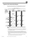
FT Output: The FT output is set if the PLC (rather than the Ethernet Interface) detects
that the COMMREQ fails. In this case, the other status indicators are not updated for
this COMMREQ. See Section 3 for more information.
The COMMREQ Command Block
When the COMMREQ function is initiated, the Command Block is sent from the PLC
CPU to the Ethernet Interface. The Command Block contains the details of a Channel
Command to be performed by the Interface.
The address in CPU memory of the Command Block is specified by the IN input of the
COMMREQ Function Block. This address may be in any word-oriented area of memory
(%R, %AI, or %AQ). The Command Block is set up using an appropriate programming
instruction (the BLOCK MOVE Function Block is recommended).
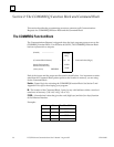
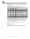
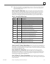
The Command Block has the following structure:
Word 1
Data Block Length (words)
Word 2 WAIT/NOWAIT Flag = 0
Word 3 CRS Word Pointer Memory Type
Word 4 CRS Word Pointer Offset
Word 5 Reserved
Word 6 Reserved
Words 7 and up Data Block (Channel Command Details)
When entering information for the Command Block, refer to these definitions:
(Word 1) Data Block Length: This is the length in words of the Data Block portion of the
Command Block. The Data Block portion starts at Word 7 of the Command Block. The
length is measured from the beginning of the Data Block at Word 7, not from the begin-
ning of the Command Block. The correct value for each command, and the associated
length of each command, is specified in Section 3.
(Word 2) WAIT/NOWAIT Flag: This flag must be set to zero for TCP/IP Ethernet Commu-
nications.