


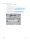

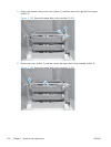
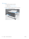
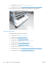

3. Remove one screw (callout 1), and then remove the left cover (callout 2) from the HCI.
Figure 1-200 Remove the HCI left cover (2 of 2)
2
1
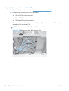
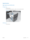
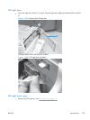
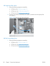
HCI left lower cover
1. Remove the following components or assemblies:
●
HCI left tray. See
HCI left tray on page 131.
●
HCI left cover. See
HCI left cover on page 132.
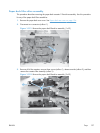
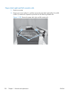
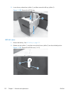
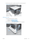
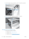
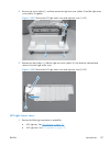
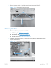
2. Remove three screws (callout 1), and then remove the left lower cover (callout 2).
Figure 1-201 Remove the HCI left lower cover
2
1
ENWW
Input devices
133