


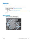
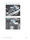
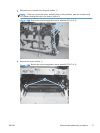
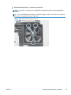

2. Release the wire harness from the guide (callout 1).
NOTE: When you remove the sensor assembly later in this procedure, pass the connector and
wire harness through the hole in the chassis (callout 2).
Figure 1-125 Remove the color-misregistration sensor assembly PCA (2 of 4)
1
2
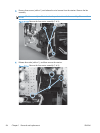
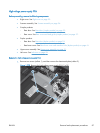
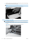
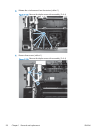
3. Remove two screws (callout 1).
Figure 1-126 Remove the color-misregistration sensor assembly PCA (3 of 4)
1
ENWW
Removal and replacement procedures
91