


Component locations
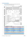
The following figure and table describe the system board component layout.
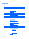
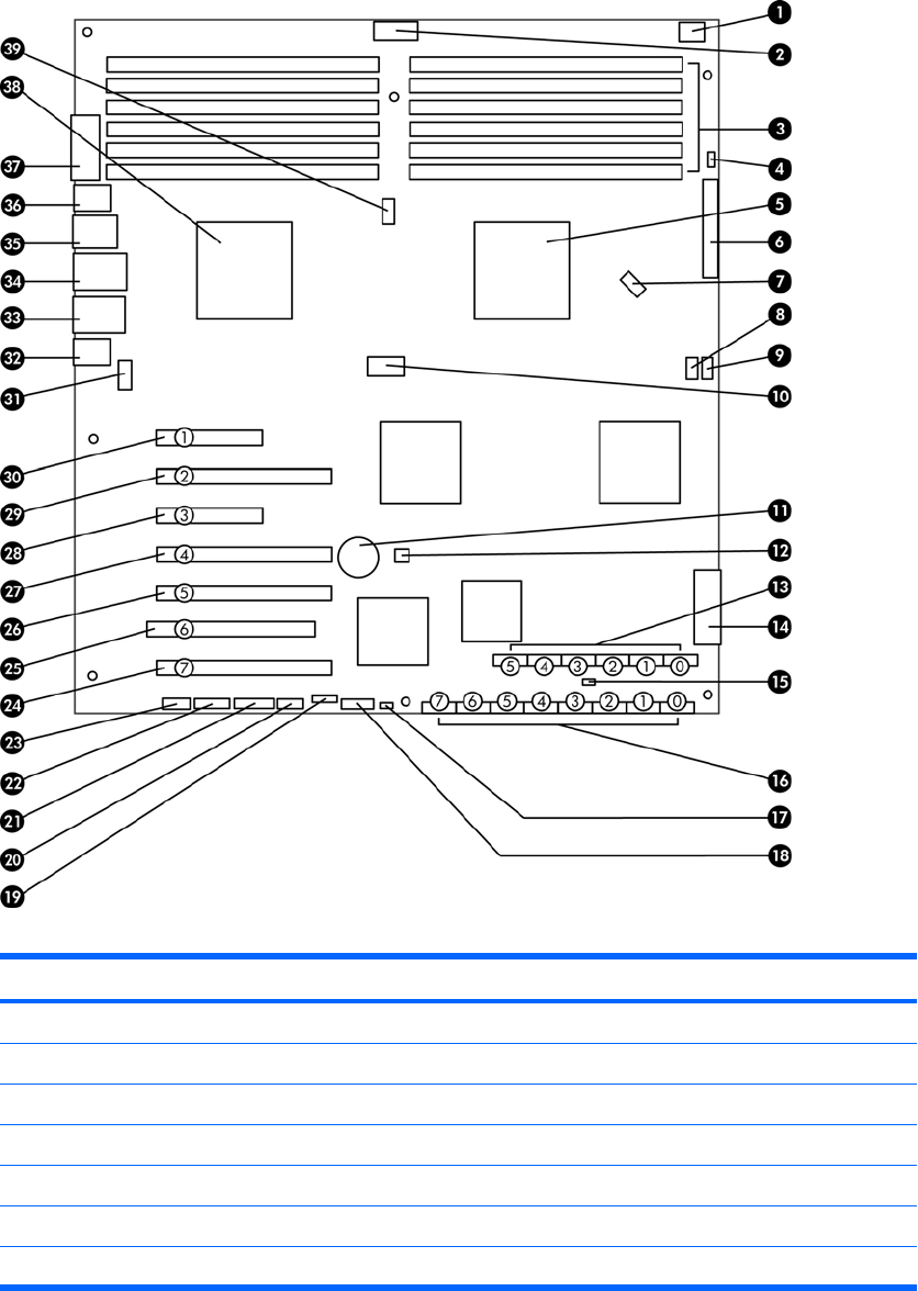
Figure 5-1 System board component locations
Table 5-2 System board components ID
Item Component Item Component Item Component
1 Memory fans 14 Main power 27 PCIe2 x16(8)
2 Memory power 15 HDD LED 28 PCIe x8(4)
1
3 Memory sockets 16 SAS connectors 29 PCIe2 x16
4 Crisis recovery jumper 17 Password jumper 30 PCIe2 x8(4)
1
5 CPU1 socket 18 Front USB 31 Rear system fan
6 Flexible disk drive 19 Internal USB-1 32 Audio
7 CPU1 fan 20 Internal USB-2/DASH 33 Network/USB
70 Chapter 5 Replacing components ENWW