


HP Omnibook XE3 (Technology Codes GE and GD) Removal and Replacement 2-1
2
Removal and Replacement
This chapter shows how to remove and replace the notebook’s components and assemblies. The items
marked by
•
in the following table are user-replaceable.
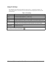
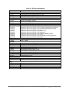
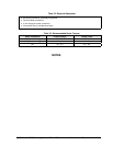
Table 2-1. Removal Cross-Reference
•
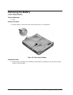
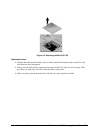
Battery (page 2-4).
Carrier, hard disk drive (page 2-15).
Case, bottom (page 2-35).
Case, top (page 2-22).
Cover, keyboard (page 2-10).
•
Cover, mini-PCI (page 2-9).
•
Cover, SDRAM (page 2-9).
•
Covers, screw (page 2-9).
Display assembly (page 2-18).
Doors, PCMCIA (page 2-38).
Drive, CD/DVD (page 2-34).
Drive, floppy disk (page 2-32).
Drive, hard disk (page 2-14).
Heatsink assembly (with fan) (page 2-29).
Keyboard (page 2-12).
Module, CPU (page 2-30).
•
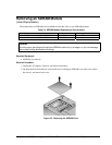
Module, SDRAM (page 2-5).
PCA, CD player (page 2-24).
PCA, headphone (page 2-41).
•
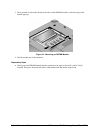
PCA, mini-PCI (page 2-7).
PCA, motherboard (page 2-35).
PCA, switchboard (page 2-41).
PCA, video (page 2-27).
Saddle, hinge set (page 2-25).
Socket, PCMCIA (page 2-41).
Caution
Always provide proper grounding when performing repairs. Without proper
grounding, an electrostatic discharge can damage the notebook and its
components.
Notes
To reassemble a component, perform the removal procedure in reverse order. Any special notes
required for reassembly are included at the end of each section.
Symbols like this throughout this chapter show approximate full-size screw outlines. You can
use these to verify the sizes of screws before you install them. Installing a wrong-size screw can
damage the notebook. (The symbol at the left represents an M2.5×5 mm T-head screw.)