


L2002 Inverter
Configuring
Drive Parameters
3–35
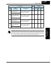
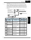
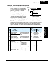
Electronic Thermal Overload Alarm Setting
The thermal overload detection protects the
inverter and motor from overheating due to
an excessive load. It uses a current/inverse
time curve to determine the trip point.
First, use B013 to select the torque charac-
teristic that matches your load. This allows
the inverter to utilize the best thermal
overload characteristic for your application.
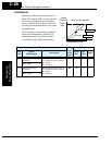
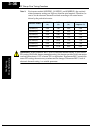
The torque developed in a motor is directly
proportional to the current in the windings,
which is also proportional to the heat generated (and temperature, over time). Therefore,
you must set the thermal overload threshold in terms of current (amperes) for parameter
B012. The range is 20% to 120% of the rated current for each inverter model. If the
current exceeds the level you specify, the inverter will trip and log an event (error E05) in
the history table. The inverter turns the motor output OFF when tripped. Separate
settings are available for the second motor (if applicable) as shown in the following
table.
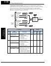
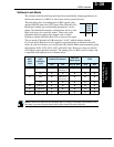
Output frequency
Constant torque
Reduced
torque
B013
=
01
B013
=
00
Tor qu e
520 60 120
Hz
100%
80%
60%
0
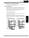
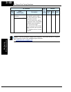
“B” Function Run
Mode
Edit
Lo Hi
Defaults
Func.
Code
Name /
SRW Display
Description
–FE(F)
(EU)
–FU
(USA)
Units
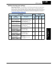
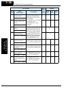
B012 Level of electronic
thermal setting
Set a level between 20% and
120% for the rated inverter
current.
✘ ✔ Rated current
for each inverter
model *1
A
E-THM LVL001.60A
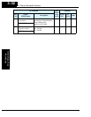
B212 Level of electronic
thermal setting, 2nd
motor
Set a level between 20% and
120% for the rated inverter
current.
✘ ✔ Rated current
for each inverter
model *1
A
2ETHM LVL 01.60A
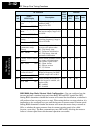
B013 Electronic thermal
characteristic
Select from two curves, option
codes:
00 .. Reduced torque 1
01 .. Constant torque
02 .. Reduced torque 2
✘ ✔ 01 01 —
E-THM CHAR CRT
B213 Electronic thermal
characteristic, 2nd
motor
Select from two curves, option
codes:
00 .. Reduced torque 1
01 .. Constant torque
02 .. Reduced torque 2
✘ ✔ 01 01 —
2ETHM CHAR CRT