


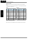
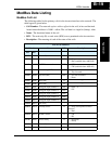
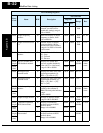
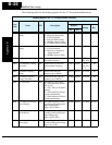
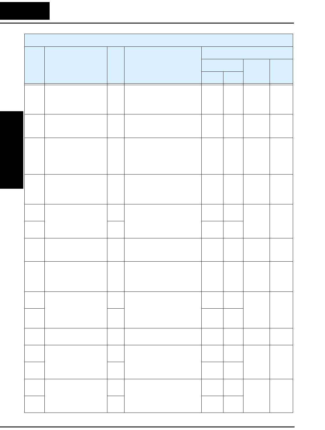
ModBus Data Listing
Appendix B
B–22
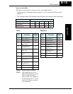
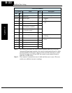
— Process Variable (PV) RW PID loop PV value from the
network (set A076=02 to
enable this setting), range is
0.0 to 100.0%
0005h 00005 0 to
1000
0.1%
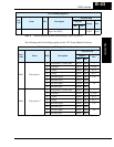
D001 Output frequency
monitor
R Real-time display of output
frequency to motor, from
0.0 to 400.0 Hz
1002h 04098 0 to
4000
0.1 Hz
D002 Output current monitor
*1
R Filtered display of output
current to motor (100 ms
internal filter time constant),
range is 0 to 200% of inverter
rated current
1003h 04099 0 to
2000
0.1%
D003 Rotation direction
monitor
R Three different indications:
00 ...Stop
01 ...Forward
02 ...Reverse
1004h 04100 0, 1, 2 —
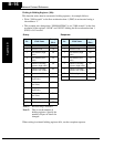
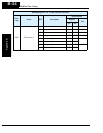
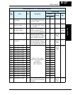
D004
(high)
Process variable (PV),
PID feedback monitor
R Displays the scaled PID
process variable (feedback)
value (A075 is scale factor),
range is 0.00 to 99900
1005h 04101 0 to
999900
0.00%
times
const.
D004
(low)
R 1006h 04102
D005 Intelligent input
terminal status
R Displays the state of the intel-
ligent input terminals [x],
Bit 0 = [1] to Bit 4 = [5]
1007h 04103 0 to 31 —
D006 Intelligent output
terminal status
R Displays the state of the intel-
ligent output terminals [x],
Bit 0 = [11], Bit 1 = [12],
Bit 2 = [AL]
1008h 04104 0 to 7 —
D007
(high)
Scaled output frequency
monitor
R Displays the output frequency
scaled by the constant in
B086. Decimal point indicates
range:
0.00 to 99999
1009h 04105 0 to
999999
0.01 Hz
times
const.
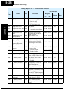
D007
(low)
R 100Ah 04106
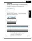
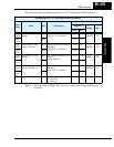
D013 Output voltage monitor R Voltage of output to motor,
range is 0.00 to 200.00%
100Ch 04108 0 to
20000
0.01%
D016
(high)
Cumulative operation
RUN time monitor
R Displays total time the
inverter has been in RUN
mode in hours.
Range is 0 to 999000
100Eh 04110 0 to
999999
1 hour
D016
(low)
R 100Fh 04111
D017
(high)
Cumulative power-on
time monitor
R Displays total time the
inverter has been in RUN
mode in hours.
Range is 0 to 999000
1010h 04112 0 to
999999
1 hour
D017
(low)
R 1011h 04113
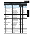
List of Holding Registers
Func.
Code
Name R/W Description
Network Data
Reg.ister
Range Res.
hex dec.