


L2002 Inverter
Configuring
Drive Parameters
3–57
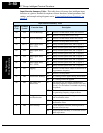
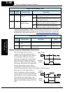
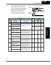
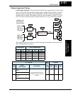
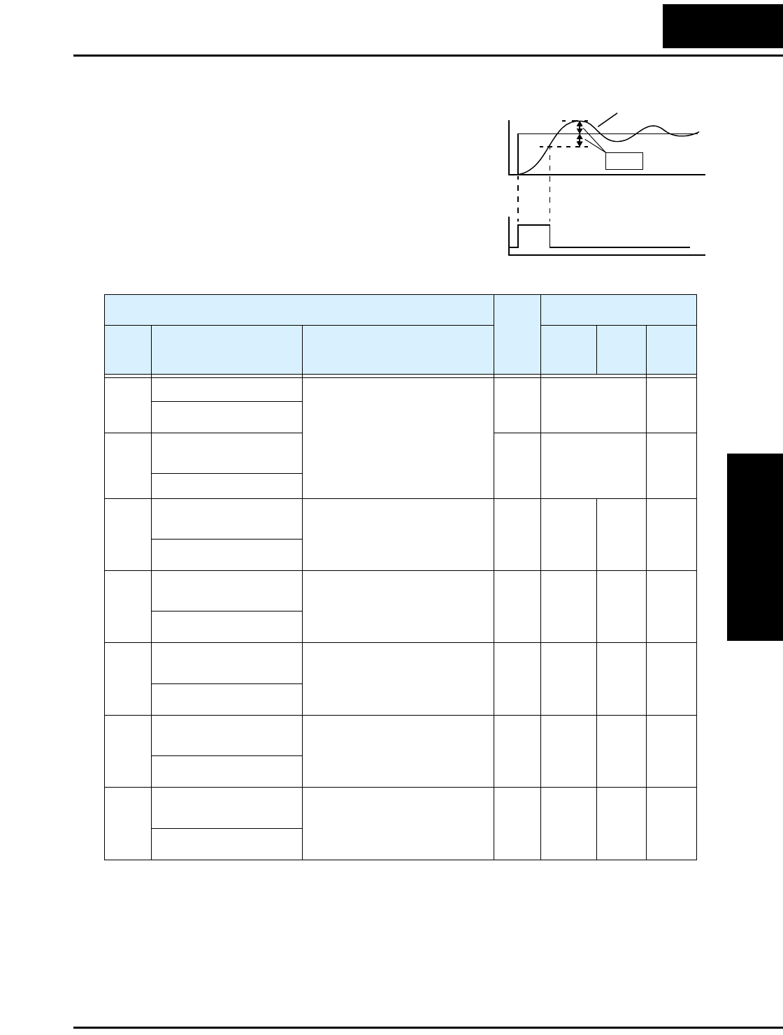
The Error for the PID loop is the magni-
tude (absolute value) of the difference
between the Setpoint (desired value) and
Process Variable (actual value). The PID
output deviation signal [OD] (output
terminal function option code 04)
indicates when the error magnitude has
exceeded a magnitude you define.
PID Error (PV–SP) deviation threshold
Deviation
signal
t
t
SP
Output
PV
0
1
0
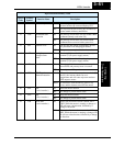
C044
“C” Function Run
Mode
Edit
Lo Hi
Defaults
Func.
Code
Name /
SRW Display
Description
–FE(F)
(EU)
–FU
(USA)
Units
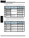
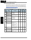
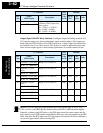
C041 Overload level setting Sets the overload signal level
between 0% and 200% (from 0
to two times the rated current
of the inverter)
✘ ✔ Rated current
for each inverter
model
A
OL LVL 001.60A
C241 Overload level setting,
2nd motor
✘ ✔ Rated current
for each inverter
model
A
2OLLVL 001.60A
C042 Frequency arrival
setting for acceleration
Sets the frequency arrival
setting threshold for the output
frequency during acceleration,
range is 0.0 to 400.0 Hz
✘ ✔ 0.0 0.0 Hz
ARV ACC 0000.0Hz
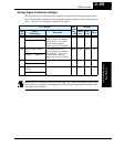
C043 Arrival frequency
setting for deceleration
Sets the frequency arrival
setting threshold for the output
frequency during deceleration,
range is 0.0 to 400.0 Hz
✘ ✔ 0.0 0.0 Hz
ARV DEC 0000.0Hz
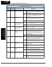
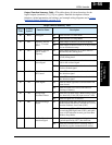
C044 PID deviation level
setting
Sets the allowable PID loop
error magnitude (absolute
value), SP - PV, range is 0.0 to
100%, resolution is 0.1%
✘ ✔ 3.0 3.0 %
ARV PID 003.0%
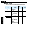
C052 PID FBV function
high limit
When the PV exceeds this
value, the PID loop turns OFF
the PID Second Stage Output,
range is 0.0 to 100.0%
✘ ✔ 100.0 100.0 %
PID LtU 0100.0%
C053 PID FBV function
variable low limit
When the PV goes below this
value, the PID loop turns ON
the PID Second Stage Output,
range is 0.0 to 100.0%
✘ ✔ 0.0 0.0 %
PID LtL 0000.0%