


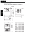
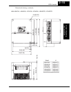
Step-by-Step Basic Installation
Inverter Mounting
and Installation
2–18
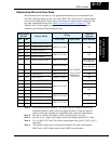
Terminal Dimensions and Torque Specs
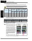
The terminal screw dimensions for all L2002 inverters are listed in table below. This
information is useful in sizing spade lug or ring lug connectors for wire terminations.
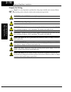
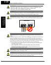
CAUTION: Fasten the screws with the specified fastening torque in the table below.
Check for any loosening of screws. Otherwise, there is the danger of fire.
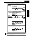
When connecting wiring, use the tightening torque listed in the following table to safely
attach wiring to the connectors.
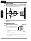
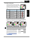
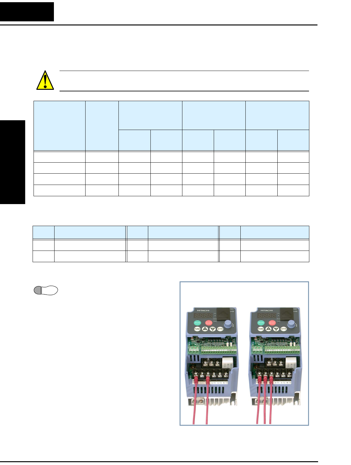
Wire the Inverter Input to a Supply
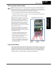
Step 6: In this step, you will connect
wiring to the input of the inverter. First,
you must determine whether the inverter
model you have requires three-phase
power only, or if it can accept either
single-phase or three-phase power. All
models have the same power connector
terminals [R/L1], [S/L2], and [T/L3].
So, you must refer to the specifications
label (on the side of the inverter) for
the acceptable power source types! For
inverters that can accept single-phase
power and are connected that way,
terminal [S/L2] will remain uncon-
nected.
The examples to the right show single-
phase and 3-phase input wiring. Note the
use of ring lug connectors for a secure connection.
Connector
Number
of Screw
Terminals
Models 002NF,
004NF, 005NF
Models 007NF-
022NF, 037LF,
004HF - 040HF
Models 055LF,
075LF, 055HF,
075HF
Screw
Diameter
Width
(mm)
Screw
Diameter
Width
(mm)
Screw
Diameter
Width
(mm)
Power Terminals 12 M3.5 7.1 M4 9 M5 13
Control Signal 16 M2 — M2 — M2 —
Alarm Signal 3 M3—M3—M3—
Ground Terminals 2 M4 — M4 — M5 —
Screw Tightening Torque Screw Tightening Torque Screw Tightening Torque
M2 0.2 N•m (max. 0.25 N•m) M3.5 0.8 N•m (max. 0.9 N•m) M5 2.0 N•m (max. 2.2 N•m)
M3 0.5 N•m (max. 0.6 N•m) M4 1.2 N•m (max. 1.3 N•m) — —
6
Single-phase
input wiring
3-phase
input wiring