


Step-by-Step Basic Installation
Inverter Mounting
and Installation
2–10
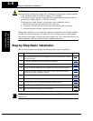
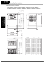
Ensure Adequate Ventilation
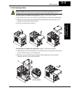
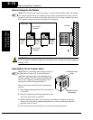
Step 2: To summarize the caution messages—you will need to find a solid, non-flamma-
ble, vertical surface that is in a relatively clean and dry environment. In order to ensure
enough room for air circulation around the inverter to aid in cooling, maintain the speci-
fied clearance around the inverter specified in the diagram.
CAUTION: Be sure to maintain the specified clearance area around the inverter and to
provide adequate ventilation. Otherwise, the inverter may overheat and cause equipment
damage or fire.
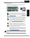
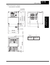
Keep Debris Out of Inverter Vents
Step 3: Before proceeding to the wiring section, it’s
a good time to temporarily cover the inverter’s
ventilation openings. Paper and masking tape are
all that is needed. This will prevent harmful debris
such as wire clippings and metal shavings from
entering the inverter during installation.
Please observe this checklist while mounting the
inverter:
1. The ambient temperature must be in the range of
–10 to 40°C.
2. Keep any other heat-producing equipment as far
away from the inverter as possible.
3. When installing the inverter in an enclosure, maintain the clearance around the
inverter and verify that its ambient temperature is within specification when the
enclosure door is closed.
4. Do not remove the front housing cover at any time during operation.
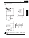
2
10 cm (3.94”)
minimum
10 cm (3.94”)
minimum
Clear area
Air flow
L2002
1
2
RUN
STOP
RESET
FUNC.
STR
HITACHI
POWER
ALARM
RUN
A
Hz
PRG
5 0.0
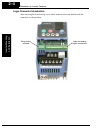
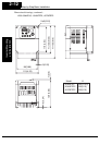
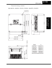
2 cm
(0.79”)
min.
2 cm
(0.79”)
min.
2 cm
(0.79”)
min.
L2002
1
2
RUN
STOP
RESET
FUNC.
STR
HITACHI
POWER
ALARM
RUN
A
Hz
PRG
5 0.0
3
Ventilation holes
(both sides)
Ventilation holes
(top)