“D” Group: Monitoring Functions
Configuring
Drive Parameters
3–8
Local Monitoring During Network Operation
The L2002 inverter’s serial port may be connected to a network or to an external digital
operator. During those times, the inverter keypad keys will not function (except for the
Stop key). However, the inverter’s 4-digit display still provides the Monitor Mode
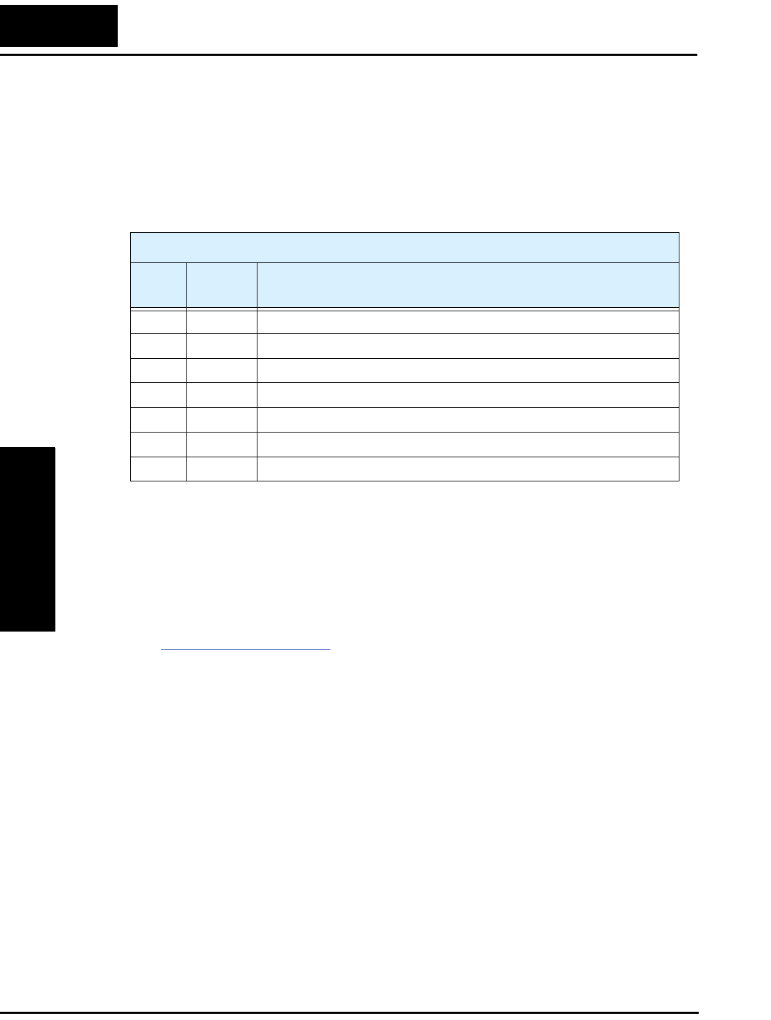
function, displaying any of the parameters D001 to D007. Function B089, Monitor
Display Select for Networked Inverter, determines the particular D00x parameter
displayed. Refer to the table below.
When monitoring the inverter during network operation, please note the following:
• The inverter display will monitor D00x functions according to B089 setting when...
• the OPE/485 DIP switch is set to the “485” position, or
• a device is already connected to the inverter’s serial port at inverter powerup.
• During network operation, the inverter keypad will also display error codes for
inverter trip events. Use the Stop key or inverter Reset function to clear the error. Refer
to “
Error Codes” on page 6–5 to interpret the error codes.
• The Stop key can be disabled, if you prefer, by using function B087.
B089 Monitor Display Select for Networked Inverter
Option
Code
Monitor
Code
Monitor Function Name
01 D001 Output frequency monitor
02 D002 Output current monitor
03 D003 Rotation direction monitor
04 D004 Process variable (PV), PID feedback monitor
05 D005 Intelligent input terminal status
06 D006 Intelligent output terminal status
07 D007 Scaled output frequency monitor


