


L2002 Inverter
Configuring
Drive Parameters
3–37
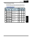
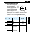
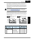
Overload Restriction
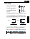
If the inverter’s output current exceeds a
preset current level you specify during
acceleration or constant speed, the overload
restriction feature automatically reduces the
output frequency to restrict the overload.
This feature does not generate an alarm or
trip event. You can instruct the inverter to
apply overload restriction only during
constant speed, thus allowing higher
currents for acceleration. Or, you may use
the same threshold for both acceleration and
constant speed.
When the inverter detects an overload, it
must decelerate the motor to reduce the current until it is less than the threshold. You can
choose the rate of deceleration that the inverter uses to lower the output current.
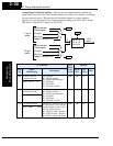
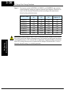
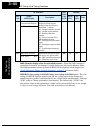
The overload restriction level can be set to a constant or to a variable (analog input). For
constant values, use B028/B228 = 00 to select parameters B022/B222. For a variable
overload restriction level, use B028/B228 = 01 to select analog voltage input terminals
[O]–[L]. In this case, parameters A013 and A014 set the start and end points for the
linear range of the graph as shown in the graphs below.
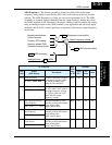
When using the analog input method to set the overload restriction (B028/B228 = 01),
the inverter does not read settings B022/B222 Overload Restriction Level. Instead, the
inverter writes the analog input value (in Ampere units) to parameters B022/B222. In
this way, you can monitor the effective overload restriction value (in Amperes) in real
time. However, you cannot store the value to B022/B222. If you use the second motor
function, the inverter displays “void” for either B022 or B222 if the parameter’s corre-
sponding motor is not selected via Set or Special Set functions.
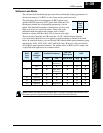
Input State B022 monitor display B222 monitor display Units
[SET] or [S-ST]
OFF [O] analog input value
void
A
ON
void
[O] analog input value A
Motor
Current
Output
frequency
t
t
Restriction area
0
0
B022
B023
Overload
restriction
level
[O]–[L] input
10%
150%
0V 10V
10%
150%
0V 10V
Overload
restriction
level
[O]–[L] input
A013
=
0 A014
=
100 A013
=
20 A014
=
80
28