


L2002 Inverter
Configuring
Drive Parameters
3–59
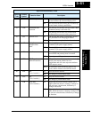
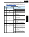
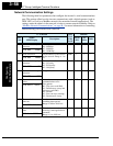
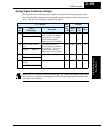
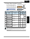
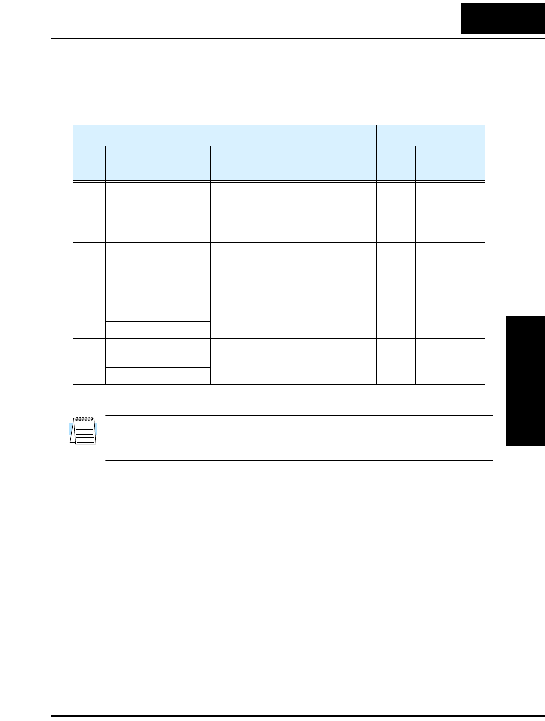
Analog Signal Calibration Settings
The functions in the following table configure the signals for the analog output termi-
nals. Note that these settings do not change the current/voltage or sink/source character-
istics—only the zero and span (scaling) of the signals.
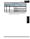
NOTE: When you restore factory default settings, the values will change to those listed
above. Be sure to manually reconfigure the values for your application, if needed, after
restoring factory defaults.
“C” Function Run
Mode
Edit
Lo Hi
Defaults
Func.
Code
Name /
SRW Display
Description
–FE(F)
(EU)
–FU
(USA)
Units
C081 O input span calibration Scale factor between the
external frequency command
on terminals L – O (voltage
input) and the frequency
output, range is 0.0 to 200.0%
✔ ✔ 100.0 100.0 %
O-ADJ 0100.0%
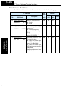
C082 OI input span calibra-
tion
Scale factor between the
external frequency command
on terminals L – OI (current
input) and the frequency
output, range is 0.0 to 200.0%
✔ ✔ 100.0 100.0 %
OI-ADJ 0100.0%
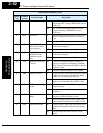
C085 Thermistor input tuning Range is 0.0 to 200.0% ✔ ✔ 100.0 100.0 %
PTC Adj 0100.0%
C086 [AM] terminal offset
tuning
Range is 0.0 to 10.0V ✔ ✔ 0.0 0.0 V
AM-OFFST 0000.0V