


Intel
®
IXP45X and Intel
®
IXP46X Product Line of Network Processors
February 2007 HDD
Document Number: 305261; Revision: 004 17
General Hardware Design Considerations—Intel
®
IXP45X and Intel
®
IXP46X Product Line of
Network Processors
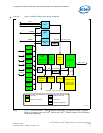
3.0 General Hardware Design Considerations
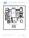
This chapter contains information for implementing and interfacing to major hardware
blocks of the Intel
®
IXP45X and Intel
®
IXP46X Product Line of Network Processors.
Such blocks include DDR SDRAM, Flash, SRAM, Ethernet PHYs, UART and most other
peripherals interfaces. Signal definition tables list resistor recommendations for pull-
ups and pull-downs.
Features disabled by a specific part number, do not require pull-ups or pull-downs.
Therefore, all pins can be left unconnected. Features enabled by a specific part number
and required to be Soft Fuse-disabled, only require pull-ups or pull-downs in the clock-
input signals. Other conditions may require pull-up or pull-down resistors for
configuration purposes at power on or reset. Likewise, open-collector outputs must be
pulled-high.
Warning: The IXP45X/IXP46X network processors’ I/O pins are 3.3 V only, except for DDR
SDRAM which is 2.5 V. None of the I/Os are 5-V tolerant.
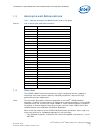
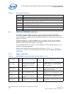
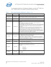
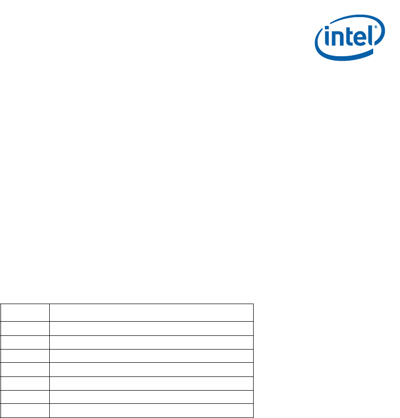
Table 2 gives the legend for interpreting the Type field used in this chapter’s signal-
definition tables.
3.1 Soft Fusible Features
Soft Fuse Enable/Disable is a method to enable or disable features in hardware,
virtually disconnecting the hardware modules from the processor.
Some of the features offered in the IXP45X/IXP46X product line can be Soft Fuse
Enabled/Disabled during boot. It is recommended that if a feature is not used in the
design, the feature be Soft disabled. This helps reduce power and maintain the part
running at a cooler temperature. When Soft Fuse Disabled, a pull-up resistor must be
connected to each clock input pins of the disabled feature interface. All other signals
can be left unconnected.
Soft Fuse Enable/Disable can be done by writing to EXP_UNIT_FUSE_RESET register,
for more information refer to the Intel
®
IXP45X and Intel
®
IXP46X Product Line of
Network Processors Developer’s Manual and review the register description.
Table 2. Signal Type Definitions
Symbol Description
I Input pin only
O Output pin only
I/O Pin can be either an input or output
OD Open-drain pin
TRI Tri-State pin
PWR Power pin
GND Ground pin