


Intel
®
IXP45X and Intel
®
IXP46X Product Line of Network Processors—General Hardware
Design Considerations
Intel
®
IXP45X and Intel
®
IXP46X Product Line of Network Processors
HDD February 2007
42 Document Number: 305261; Revision: 004
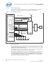
3.9.1 Signal Interface
3.9.2 Device Connection
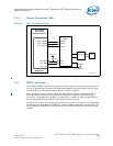
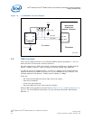
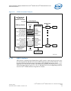
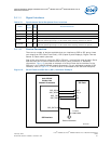
The following example shown in Figure 13 shows a typical interface to an ADSL Framer
via the UTOPIA bus. Notice that depending on the framer used some control signals
might be required which can be derived from the Expansion bus or the GPIO signals.
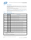
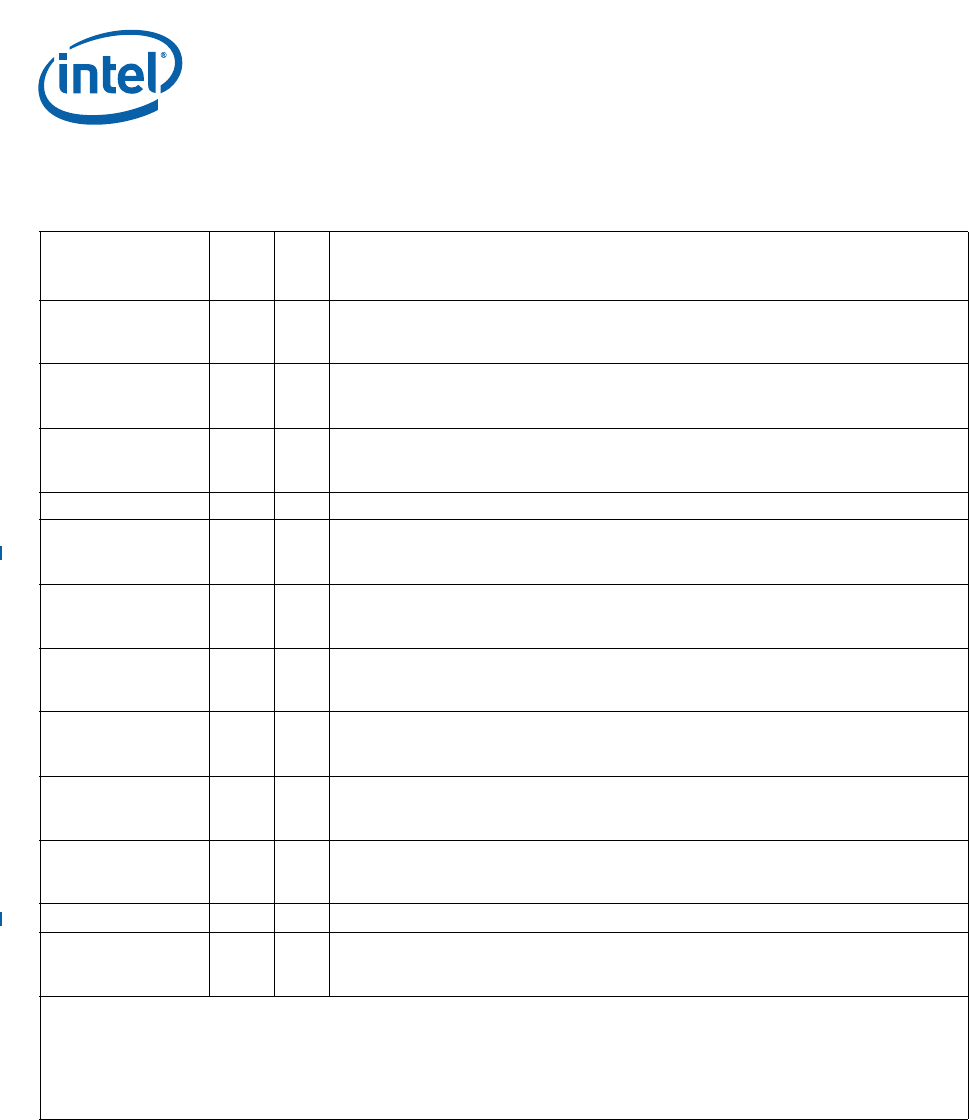
Table 16. UTOPIA Signal Recommendations
Name
Input/
Output
Pull
Up/
Down
Recommendations
UTP_OP_CLK I Yes
UTOPIA Transmit clock input. Also known as UTP_TX_CLK.
When this interface/signal is enabled and is not being used in a system design, the
interface/signal should be pulled high with a 10-KΩ resistor.
UTP_OP_FCO O Yes
UTOPIA flow control output signal. Also known as the TXENB_N signal.
When this interface/signal is enabled and is not being used in a system design, the
interface/signal should be pulled high with a 10-KΩ resistor.
UTP_OP_SOC O Yes
Start of Cell. Also known as TX_SOC.
When this interface/signal is enabled and is not being used in a system design, the
interface/signal should be pulled low with a 10-KΩ resistor.
UTP_OP_DATA[7:0] O No UTOPIA output data.
UTP_OP_ADDR[4:0] I/O Yes
Transmit PHY address bus.
When this interface/signal is enabled and is not being used in a system design, the
interface/signal should be pulled high with a 10-KΩ resistor.
UTP_OP_FCI I Yes
UTOPIA Output data flow control input: Also known as the TXFULL/CLAV signal.
When this interface/signal is enabled and is not being used in a system design, the
interface/signal should be pulled high with a 10-KΩ resistor.
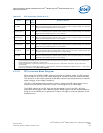
UTP_IP_CLK I Yes
UTOPIA Receive clock input. Also known as UTP_RX_CLK.
When this interface/signal is enabled and is not being used in a system design, the
interface/signal should be pulled high with a 10-KΩ resistor.
UTP_IP_FCI I Yes
UTOPIA Input Data flow control input signal. Also known as RXEMPTY/CLAV.
When this interface/signal is enabled and is not being used in a system design, the
interface/signal should be pulled high with a 10-KΩ resistor.
UTP_IP_SOC I Yes
Start of Cell. Also known as RX_SOC
When this interface/signal is enabled and is not being used in a system design, the
interface/signal should be pulled high with a 10-KΩ resistor.
UTP_IP_DATA[7:0] I Yes
UTOPIA input data. Also known as RX_DATA.
When this interface/signal is enabled and is not being used in a system design, the
interface/signal should be pulled high with a 10-KΩ resistor.
UTP_IP_ADDR[4:0] I/O No Receive PHY address bus.
UTP_IP_FCO O Yes
UTOPIA Input Data Flow Control Output signal: Also known as the RX_ENB_N.
When this interface/signal is enabled and is not being used in a system design, the
interface/signal should be pulled high with a 10-KΩ resistor.
Notes:
1. Features disabled/enabled by Soft Fuse must be done during the boot-up sequence. A feature cannot be enabled after
being disabled without asserting a system reset.
2. Features disabled by a specific part number, do not require pull-ups or pull-downs. Therefore, all pins can be left
unconnected.
3. Features enabled by a specific part number — and required to be Soft Fuse-disabled, as stated in Note 1 — only require
pull-ups or pull-downs in the
clock-input signals.