


Intel
®
IXP45X and Intel
®
IXP46X Product Line of Network Processors—Category
Intel
®
IXP45X and Intel
®
IXP46X Product Line of Network Processors
HDD February 2007
66 Document Number: 305261; Revision: 004
5.2.2 Clock Signal Considerations
• Provide good return current paths for clock traces.
• Keep clock traces away from the edge of the board and any other high-speed
devices or traces.
• Keep clock traces away from analog signals, including voltage reference signals.
• Clock signals should not cross over a split plane.
• Route clock signals in a single, internal layers and eliminate routing in multiple
layers as much as possible.
• Do not route traces or vias under crystals or clock oscillators devices unless there is
a plane between the trace and the component.
• Do not route parallel signal traces directly above or below clock traces unless there
is a ground or at least a power plane separation between those layers.
• Route clock traces with a minimum number of vias.
• Space clock traces away from other signals three times the trace width on each
side.
• Use guard traces when routing on top or bottom layers whenever possible. Guard
traces must be connected to ground.
• Do not daisy-chain, instead use point-to-point clock distribution. Place a series
termination resistor as close as possible to the source.
• Keep traces short to minimize reflections and signal degradation.
• Maintain control impedance for all clock traces, microstrip or stripline.
— Be aware of propagation delays between a microstrip and stripline.
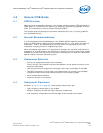
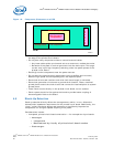
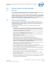
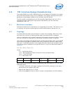
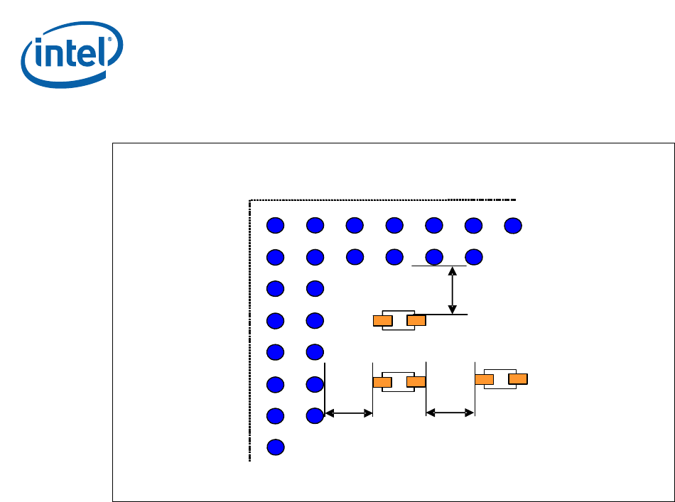
Figure 25. Pad-to-Pad Clearance of Passive Components to a PGA or BGA
B2268-01
60 mils min 60 mils min
60 mils min
PGA or BGA Package