


Intel
®
IXP45X and Intel
®
IXP46X Product Line of Network Processors—General Hardware
Design Considerations
Intel
®
IXP45X and Intel
®
IXP46X Product Line of Network Processors
HDD February 2007
56 Document Number: 305261; Revision: 004
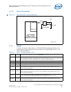
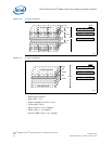
3.15.1 De-Coupling Capacitance Recommendations
It is common practice to place de-coupling capacitors between the supply voltages and
ground. Placement can be near the input supply pins and ground, with one 100-nF
capacitor per pin. Additional de-coupling capacitors can be place all over the board
every 0.5” to 1.0”. This ensures good return path for currents and reduce power surges
and high-frequency noise.
It is also recommended that 4.7-µF to 10-µF capacitors be placed every 2” to 3”.
3.15.2 VCC De-Coupling
Connect one 100-nF capacitor per each VCC pin. Placement should be as close as
possible to the pin. It is also recommended to place a 4.7-µF capacitor near the device.
Use traces as thick as possible to eliminate voltage drops in the connection.
3.15.3 VCCP De-Coupling
Connect one 100-nF capacitor per each VCCP pin. Placement should be as close as
possible to the pin. It is also recommended to place a 4.7-µF capacitor near the device.
Use traces as thick as possible to eliminate voltage drops in the connection.
3.15.4 VCCM De-Coupling
Connect one 100-nF capacitor per each VCCM pin. Placement should be as close as
possible to the pin. It is also recommended to place a 4.7-µF capacitor near the device.
Use traces as thick as possible to eliminate voltage drops in the connection.
3.15.5 Power Sequence
Power sequence is crucial for proper functioning of the IXP45X/IXP46X network
processors. For a complete description of power sequencing, see the Intel
®
IXP45X and
Intel
®
IXP46X Product Line of Network Processors Datasheet.
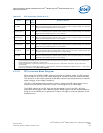
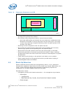
3.15.6 Reset Timing
Proper reset timing is also a crucial requirement for proper functioning of the IXP45X/
IXP46X network processors. There are two reset signal PWRON_RESET_N and
RESET_IN_N which required assertion sequence.
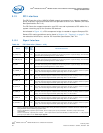
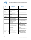
VCCPLL1 1.3 V
Supply voltage for internal logic of analog phase lock-loop circuitry. Requires special power filtering
circuitry. If operating at 667 MHz, this voltage must be increased to 1.5 V.
See the Intel
®
IXP45X and Intel
®
IXP46X Product Line of Network Processors Datasheet.
VCCPLL2 1.3 V
Supply voltage for internal logic of analog phase lock-loop circuitry. Requires special power filtering
circuitry. If operating at 667 MHz, this voltage must be increased to 1.5 V.
See the Intel
®
IXP45X and Intel
®
IXP46X Product Line of Network Processors Datasheet.
VCCPLL3 1.3 V
Supply voltage for internal logic of analog phase lock-loop circuitry. Requires special power filtering
circuitry. If operating at 667 MHz, this voltage must be increased to 1.5 V.
See the Intel
®
IXP45X and Intel
®
IXP46X Product Line of Network Processors Datasheet.
Table 24. Power Interface (Sheet 2 of 2)
Name
Nominal
Voltage
Description