


Intel
®
IXP45X and Intel
®
IXP46X Product Line of Network Processors—General Hardware
Design Considerations
Intel
®
IXP45X and Intel
®
IXP46X Product Line of Network Processors
HDD February 2007
48 Document Number: 305261; Revision: 004
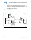
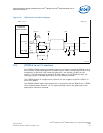
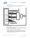
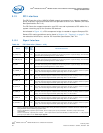
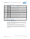
3.12 PCI Interface
The PCI Controller of the IXP45X/IXP46X network processors is an industry-standard,
32-bit interface, high-performance bus that operates at either 33 or 66 MHz (PCI Local
Bus Specification, Rev. 2.2).
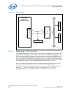
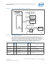
The PCI Controller supports operation as a PCI host and implements a PCI arbiter for a
system containing up to four external PCI devices.
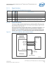
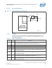
As indicated in Figure 16, a PCI transparent bridge is needed to support Compact PCI.
General PCI routing guidelines can be found in Section 6.2, “Topology” on page 71. For
more detailed information, see the PCI Local Bus Specification, Rev. 2.2.
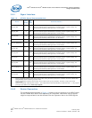
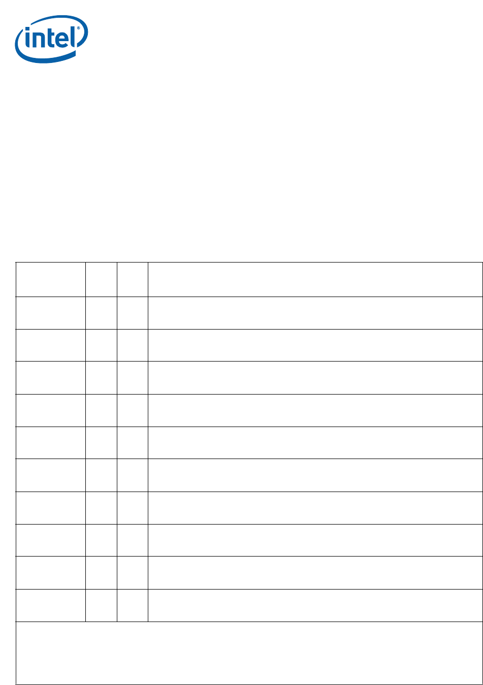
3.12.1 Signal Interface
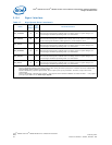
Table 20. PCI Controller (Sheet 1 of 2)
Name
Input/
Outpu
t
Pull
Up/
Down
Recommendations
PCI_AD[31:0] I/O Yes
PCI Address/Data bus.
When this interface/signal is enabled and is not being used in a system design, the interface/
signal should be pulled high with a 10-KΩ resistor.
PCI_CBE_N[3:0] I/O Yes
PCI Command/Byte Enables.
When this interface/signal is enabled and is not being used in a system design, the interface/
signal should be pulled high with a 10-KΩ resistor.
PCI_PAR I/O Yes
PCI Parity.
When this interface/signal is enabled and is not being used in a system design, the interface/
signal should be pulled high with a 10-KΩ resistor.
PCI_FRAME_N I/O Yes
PCI Cycle Frame.
When this interface/signal is enabled and is either being used or not being used in a system
design, the interface/signal should be pulled high with a 10-KΩ resistor.
PCI_TRDY_N I/O Yes
PCI Target Ready.
When this interface/signal is enabled and is either being used or not being used in a system
design, the interface/signal should be pulled high with a 10-KΩ resistor.
PCI_IRDY_N I/O Yes
Initiator Ready.
When this interface/signal is enabled and is either being used or not being used in a system
design, the interface/signal should be pulled high with a 10-KΩ resistor.
PCI_STOP_N I/O Yes
Stop.
When this interface/signal is enabled and is either being used or not being used in a system
design, the interface/signal should be pulled high with a 10-KΩ resistor.
PCI_PERR_N I/O Yes
Parity Error.
When this interface/signal is enabled and is either being used or not being used in a system
design, the interface/signal should be pulled high with a 10-KΩ resistor.
PCI_SERR_N I/O Yes
System Error.
When this interface/signal is enabled and is either being used or not being used in a system
design, the interface/signal should be pulled high with a 10-KΩ resistor.
PCI_DEVSEL_N I/O Yes
Device Select:
When this interface/signal is enabled and is either being used or not being used in a system
design, the interface/signal should be pulled high with a 10-KΩ resistor.
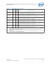
Notes:
1. Features disabled/enabled by Soft Fuse must be done during the boot-up sequence. A feature cannot be enabled after
being disabled without asserting a system reset.
2. Features disabled by a specific part number, do not require pull-ups or pull-downs. Therefore, all pins can be left
unconnected.
3. Features enabled by a specific part number — and required to be Soft Fuse-disabled, as stated in Note 1 — only require
pull-ups or pull-downs in the clock-input signals.