


Intel
®
IXP45X and Intel
®
IXP46X Product Line of Network Processors
February 2007 HDD
Document Number: 305261; Revision: 004 67
General Layout and Routing Guide—Intel
®
IXP45X and Intel
®
IXP46X Product Line of Network
Processors
— Calculate capacitive loading of all components and properly compensate with a
series or parallel terminations.
• Measure and match trace lengths for devices that interface with each other and
have their clock derived from the same source.
If traces must be long, treat them as transmission lines. Terminate clock traces to
match trace impedance.
• If there is a power plane, instead of a ground plane, make sure that the power
plane has adequate decoupling to ground, especially near clock drivers and
receivers.
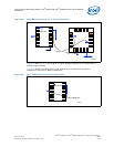
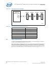
5.2.3 SMII Signal Considerations
SMII signals run at 125 MHz, single-ended and require proper trace-routing to achieve
good signal integrity and impedance matching. The following recommendations help
with designs:
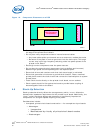
• Do not route any of the SMII signals under the IXP45X/IXP46X network processors,
or any other components, unless a ground or power plane isolates the signals.
• Minimize the number of vias to two per trace.
• Keep traces as short as possible and straight, away from other signals.
• Control impedance should maintain to 50 Ω.
• RX signals must have the same length and TX signals must have the same length.
— For the RX group, match the lengths for signals SMII_RX_SYNC,
SMII_RX_DATA, and SMII_RX_CLK.
— For TX group, match lengths for signals SMII_TX_SYNC, SMII_TX_DATA, and
SMII_TX_CLK.
• Avoid sharp corners, using 45° corners instead.
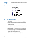
5.2.4 MII Signal Considerations
MII signals run at 25 MHz which makes them less critical that SMII. But these signals
still require certain routing guide lines.
• Minimize the number of vias to two per trace.
• Keep traces as short as possible and straight, away from other signals.
• Control impedance should maintain to 50 Ω.
• Each group either RX or TX must be length match.
• Avoid sharp corners, using 45° corners instead.
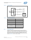
5.2.5 USB Considerations
Follow the schematic sample shown in Section 3.8, “USB Interface” on page 38 and the
recommended schematic interface.
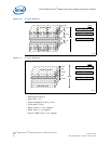
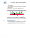
The following are recommendations for routing differential pair signal required to by
the USB interface:
• Traces can be routed in tightly couple structure with 5mil trace width and 10-mil air
gap, or maintain air gap equal 2X trace width. It is recommended these be hand-
routed.
• Match trace length for each differential pair.
• Avoid sharp corners, using 45° corners instead.