


Intel
®
IXP45X and Intel
®
IXP46X Product Line of Network Processors—General Hardware
Design Considerations
Intel
®
IXP45X and Intel
®
IXP46X Product Line of Network Processors
HDD February 2007
54 Document Number: 305261; Revision: 004
3.13.1 Signal Interface
3.14 Input System Clock
The IXP45X/IXP46X network processors require a 33.33-MHz reference clock to
generate all internal clocks required — including core clock — and the various buses
running internally within the system.
3.14.1 Clock Signals
3.14.2 Clock Oscillator
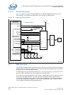
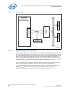
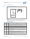
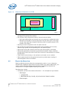
When using an external clock oscillator to supply the 33.33-MHz reference system
clock, connect the clock oscillator output to OSC_IN pin through a series termination of
33 Ω as shown in Figure 18. The series termination helps smooth the rise and fall edges
of the clock and eliminate ringing. Leave the OSC_OUT pin un-connected.
Table 22. Synchronous Serial Peripheral Port Interface
Name
Input/
Output
Pull
Up/
Down
Recommendations
JTG_TMS I Yes
Test mode select.
When the JTAG interface is not being used, the signal must be pulled high using a 10-kΩ
resistor.
JTG_TDI I Yes
Test Input data.
When the JTAG interface is not being used, the signal must be pulled high using a 10-kΩ
resistor.
JTG_TDO O O Test Output data.
JTG_TRST_N I Yes
Test Reset.
When the JTAG interface is not being used, the signal must be pulled low using a 10-kΩ
resistor.
JTG_TCK I Yes
Test Clock.
When the JTAG interface is not being used, the signal must be pulled high using a 10-kΩ
resistor.
Table 23. Clock Signals
Name Type* Description
OSC_IN I
Source must be a clock input of 33.33-MHz.
Use a series termination resistor, 10 Ω to 33 Ω at the source.
OSC_OUT O No connect
Note: For explanations of the
Type column abbreviations, see Table 2 on page 17.