


Intel
®
IXP45X and Intel
®
IXP46X Product Line of Network Processors
February 2007 HDD
Document Number: 305261; Revision: 004 69
General Layout and Routing Guide—Intel
®
IXP45X and Intel
®
IXP46X Product Line of Network
Processors
5.2.8 Trace Impedance
All signal layers require controlled impedance of 50 Ω ±10 % microstrip or stripline
(unless otherwise specified) where appropriate. Selecting the appropriate board stack-
up to minimize impedance variations is very important.
When calculating flight times, it is important to consider the minimum and maximum
trace impedance based on the switching neighboring traces.
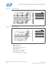
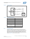
5.2.9 Power and Ground Plane
Power and ground planes should have sufficient de-coupling capacitors to ensure
sustainable current needed for high-speed switching devices. (See Section 3.15.1, “De-
Coupling Capacitance Recommendations” on page 56.)
• It is highly recommended to use sufficient internal power and ground planes.
• Due to the complexity of the IXP45X/IXP46X network processors, there are a
number of power supplies required. It is appropriate to use power islands in the
power plane under the processor, as it would be too expensive to have a power
plane for each power source.
• Power islands must be large enough to include the required power supply
decoupling capacitance, and the necessary connection to the voltage source and
destination.
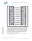
• Islands can be separated by a minimum of 20-mil air gap.
• Use at least one via per power or ground pin, wherever possible use more vias,
depending on current drawn.
• Use at least one de-coupling capacitor per power pin and place it as close as
possible to the pin.
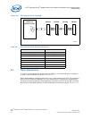
• Minimize the number of traces routed across the air gaps between power islands.
— Each crossing introduces signal degradation due to the impedance
discontinuity.
— For traces that must cross air gaps, route them on the side of the board next to
a ground plane to reduce or eliminate signal degradation caused by crossing
the gap.
— When this is not possible, then route the trace to cross the gap at a right angle
(90°).