Intel
®
IXP45X and Intel
®
IXP46X Product Line of Network Processors
February 2007 HDD
Document Number: 305261; Revision: 004 21
General Hardware Design Considerations—Intel
®
IXP45X and Intel
®
IXP46X Product Line of
Network Processors
3.3.1 Signal Interface
3.3.2 Reset Configuration Straps
At power up or whenever RESET_IN_N is asserted, the Expansion-bus address outputs
are switched to inputs and the state of the inputs are captured and stored in
Configuration Register 0, bits 24 through 0. This occurs when PLL_LOCKED is de-
asserted.
The strapping of Expansion-bus address pins can be done by placing external pull-down
resistors at the required address pin. It is not required to use external pull-up resistors,
by default upon reset all bits on Configuration Register 0 are set High, unless an
external pull down is used to set them Low. For example to register a bit low or high in
the Configuration Register 0, do the following:
Place an external 4.7-KΩ pull-down resistor to set a bit LOW.
No external pull-up is required, by default upon reset, bits are set HIGH.
The state of the boot-strapping resistor is register on the first cycle after the
synchronous de-assertion of the reset signal. These bits can be read or written as
needed for desired configurations. It is recommended that only Bit 31, Memory Map, be
changed from 1 to 0 after execution of boot code from external flash.
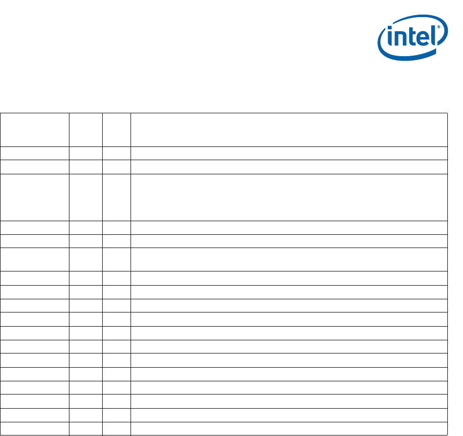
Table 5. Expansion Bus Signal Recommendations
Name
Input
Output
Pull
Up
Down
Recommendations
EX_CLK I No Use series termination resistor, 10Ω to 33Ω at the source.
EX_ALE TRI O No Use series termination resistor, 10Ω to 33Ω at the source.
EX_ADDR[24:0] I/O Yes
Use 4.7-KΩ resistors for pull-downs; required for boot strapping for initial configuration of
Configuration Register 0. Pull-ups are not required as for when the system comes out of
reset, all bits are initially set HIGH. For more details, see Table 6.
For additional details on address strapping, see the Intel
®
IXP45X and Intel
®
IXP46X
Product Line of Network Processors Developer’s Manual.
EX_WR_N I/O No Use series termination resistor, 10Ω to 33Ω at the source.
EX_RD_N I/O No Use series termination resistor, 10Ω to 33Ω at the source.
EX_CS_N[7:0] I/O Yes
Use series termination resistor, 10Ω to 33Ω at the source.
Use 10KΩ resistors pull-ups to ensure that the signal remains de-asserted.
EX_DATA[31:0] I/O No
EX_BE_N[3:0] I/O No
EX_IOWAIT_N I Yes Should be pulled high through a 10-KΩ resistor when not being utilized in the system.
EX_RDY_N[3:0] I Yes Should be pulled high through a 10-KΩ resistor when not being utilized in the system.
EX_PARITY[3:0] I/O No
EX_REQ_N[3:1] I Yes Should be pulled high through a 10-KΩ resistor when not being utilized in the system.
EX_REQ_GNT_N I Yes Should be pulled high through a 10-KΩ resistor when not being utilized in the system.
EX_GNT_N[3:1] O No
EX_GNT_REQ_N O No
EX_SLAVE_CS_N I Yes Should be pulled high through a 10-KΩ resistor when not being utilized in the system.
EX_BURST I Yes Should be pulled high through a 10-KΩ resistor when not being utilized in the system.
EX_WAIT_N TRI O No


