


Intel
®
IXP45X and Intel
®
IXP46X Product Line of Network Processors—Category
Intel
®
IXP45X and Intel
®
IXP46X Product Line of Network Processors
HDD February 2007
68 Document Number: 305261; Revision: 004
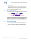
• Wherever possible, use a perfect symmetry within a differential pair.
• Minimize the number vias.
• Avoid routing other signals close by or in parallel to the differential pair,
maintaining no less than 50 mil to any other signal.
• Maintain control impedance for each differential pair to 90 Ω +/- 15 Ω.
• Use high value ferrite beads (100 MHz/60 Ω – 100 MHz/240 Ω).
5.2.6 Cross-Talk
Cross-talk is caused by capacitance and inductance coupling between signals. It is
composed of both backward and forward cross-talk components.
Backward cross-talk creates an induced signal on the network that propagates in the
opposite direction of the aggressor signal. Forward cross-talk creates a signal that
propagates in the same direction as the aggressor signal.
Circuit board analysis software should be used to analyze your board layout for cross-
talk problems.
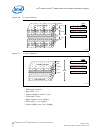
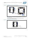
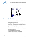
• To effectively route signals on the PCB, signals are grouped (address, data, etc.).
— The space between groups can be 3 w (where w is the width of the traces).
— Space within a group can be just 1 w.
— Space between clock signals or clock to any other signal should be 3 w. The
coupled noise between adjacent traces decreases by the square of the distance
between the adjacent traces.
5.2.7 EMI-Design Considerations
It is strongly recommended that good electromagnetic interference (EMI) design
practices be followed when designing with the IXP45X/IXP46X network processors.
• Information on spread-spectrum clocking is available in Intel
®
IXP4XX Product Line
of Network Processors and IXC1100 Control Plane Processor: Spread-Spectrum
Clocking to Reduce EMI Application Note.
• Place high-current devices as closely as possible to the power sources.
• Proper termination of signals can reduce reflections, which may emit a high-
frequency component that may contribute to more EMI than the original signal
itself.
• Ferrite beads may be used to add high frequency loss to a circuit without
introducing power loss at DC and low frequencies. They are effective when used to
absorb high-frequency oscillations from switching transients or parasitic
resonances within a circuit.
• Keep rise and fall times as slow as possible. Signals with fast rise and fall times
contain many high-frequency harmonics which may radiate significantly.
• A solid ground is essential at the I/O connector to chassis and ground plane.
• Keep the power plane shorter than the ground plane by at least 5x the spacing
between the power and ground planes.
• Stitch together all ground planes around the edge to the board every 100 to
200 mil. This helps reduce EMI radiating out of the board from inner layers.