


Intel
®
IXP45X and Intel
®
IXP46X Product Line of Network Processors
February 2007 HDD
Document Number: 305261; Revision: 004 39
General Hardware Design Considerations—Intel
®
IXP45X and Intel
®
IXP46X Product Line of
Network Processors
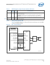
3.8.1 Signal Interface
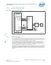
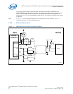
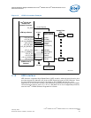
A typical implementation of a USB interface Host down-stream is shown in Figure 11.
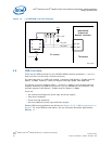
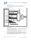
The Host controller can not be used as a Device controller; however there is a second
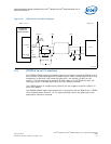
USB module with a Device controller capability that can be implementation for this
application as shown in Figure 12. Note that depending on the data rate required, Low-
speed or Full-speed, the 1.5K resistor shown near the device interface must be
connected, either on the D+ or D-.
Speed configuration at the Device can be set as stated in note 1 and 2 bellow. For more
details, refer to the Universal Serial Bus Specification, Revision 1.1.
Note:
1. If a 1.5-KΩ, pull-up resistor is connected to USB_DPOS line, the USB port is
identified as Full-speed (12 Mbps).
2. If a 1.5-KΩ, pull-up resistor is connected to USB_DNEG line, the USB port is
identified as Low-speed (1.5 Mbps).
3. The processors’ USB drivers are CMOS. They require series termination resistors on
both signals of the differential pair USB_DPOS and USB_DNEG. The value of the
series resistor depends upon the variation of the driver’s impedance.
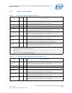
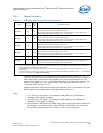
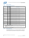
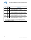
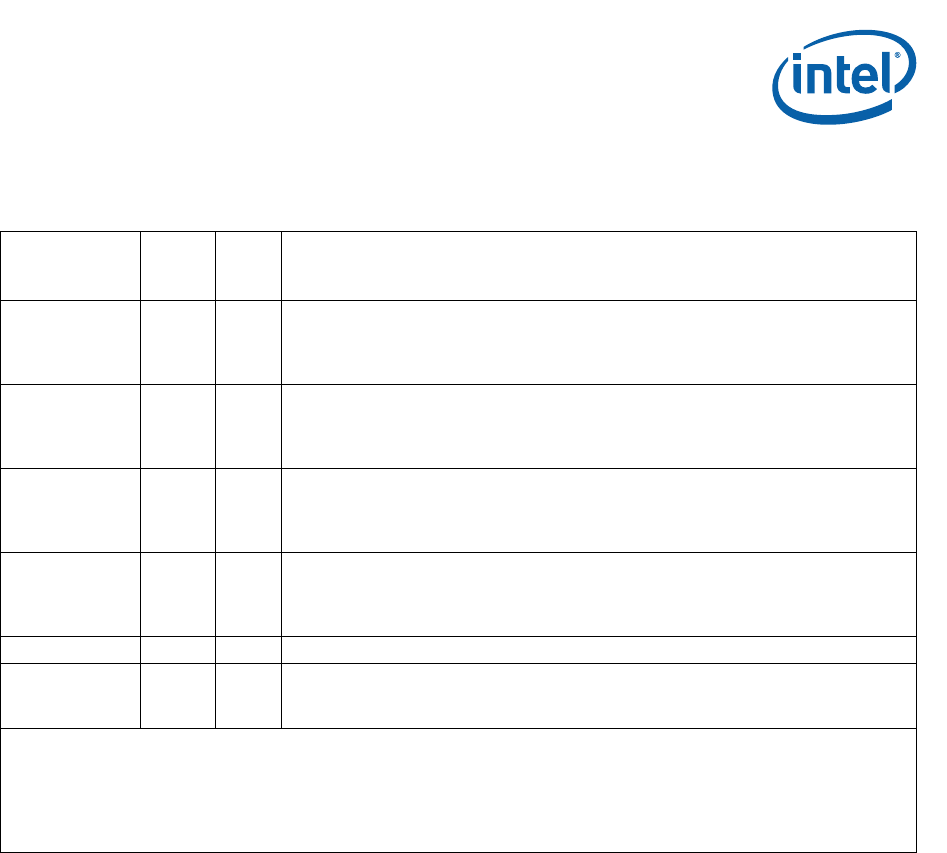
Table 15. USB Host/Device Signal Recommendations
Name
Input/
Output
Pull
Up/
Down
Recommendations
USB_DPOS I/O Yes
Positive signal of the differential USB receiver/driver for the USB device interface.
Use an 18Ω series termination resistor at the source.
When this interface/signal is enabled and is not being used in a system design, the
interface/signal should be pulled low with a 10-KΩ resistor.
USB_DNEG I/O Yes
Negative signal of the differential USB receiver/driver for the USB device interface.
Use an 18Ω series termination resistor at the source.
When this interface/signal is enabled and is not being used in a system design, the
interface/signal should be pulled low with a 10-KΩ resistor.
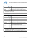
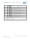
USB_HPOS I/O Yes
Positive signal of the differential USB receiver/driver for the USB host interface.
Use a 20Ω series termination resistor at the source.
When this interface/signal is enabled and is not being used in a system design, the
interface/signal should be pulled low with a 10-KΩ resistor.
USB_HNEG I/O Yes
Negative signal of the differential USB receiver/driver for the USB host interface.
Use a 20Ω series termination resistor at the source.
When this interface/signal is enabled and is not being used in a system design, the
interface/signal should be pulled low with a 10-KΩ resistor.
USB_HPEN O No Enable to the external VBUS power source
USB_HPWR I Yes
External VBUS power.
When this interface/signal is enabled and is not being used in a system design, the
interface/signal should be pulled high with a 10-KΩ resistor.
Notes:
1. Features disabled/enabled by Soft Fuse must be done during the boot-up sequence. A feature cannot be enabled after
being disabled without asserting a system reset.
2. Features disabled by a specific part number, do not require pull-ups or pull-downs. Therefore, all pins can be left
unconnected.
3. Features enabled by a specific part number — and required to be Soft Fuse-disabled, as stated in Note 1 — only required
pull-ups or pull-downs in the clock-input signals.