


Intel
®
IXP45X and Intel
®
IXP46X Product Line of Network Processors
February 2007 HDD
Document Number: 305261; Revision: 004 59
General PCB Guide—Intel
®
IXP45X and Intel
®
IXP46X Product Line of Network Processors
4.0 General PCB Guide
4.1 PCB Overview
Beginning with components selection, this chapter presents general PCB guidelines. In
cases where it is too difficult to adhere to a guideline, engineering judgment must be
used. The methods are listed as simple DOs and DON’Ts.
This chapter does not discuss the functional aspects of any bus, or layout guides for
any interfaced devices.
4.2 General Recommendations
It is recommended that boards based on the IXP45X/IXP46X network processors
employ a PCB stackup yielding a target impedance of 50 Ω ± 10% with 5 mil nominal
trace width. That is, the impedance of the trace when not subjected to the fields
created by changing current in neighboring traces.
When calculating flight times, it is important to consider the minimum and maximum
impedance of a trace based on the switching of neighboring traces. Using wider spaces
between the traces can minimize this trace-to-trace coupling. In addition, these wider
spaces reduce cross-talk and settling time.
4.3 Component Selection
• Do not use components faster than necessary
Clock rise (fall) time should be as slow as possible, as the spectral content of the
waveform decreases
• Use components with output drive strength (slew-rate) controllable if available
• Use SMT components (not through-hole components) as through-hole (leaded)
components have more stub inductance due to the protruding leads.
• Avoid sockets when possible
• Minimize number of connectors
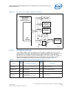
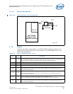
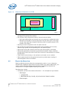
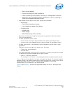
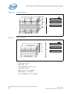
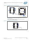
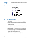
4.4 Component Placement
As shown in Figure 19 on page 60, when placing components, put:
• High-frequency components in the middle
• Medium-frequency around the high-frequency components
• Low-frequency components around the edge of the printed circuit board