


Intel
®
IXP45X and Intel
®
IXP46X Product Line of Network Processors
February 2007 HDD
Document Number: 305261; Revision: 004 23
General Hardware Design Considerations—Intel
®
IXP45X and Intel
®
IXP46X Product Line of
Network Processors
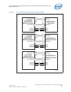
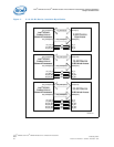
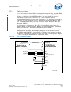
3.3.3 8-Bit Device Interface
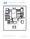
The IXP45X/IXP46X network processors support 8-bit-wide data bus devices (byte
mode). For Intel interface cycles, the data lines and control signals can be connected as
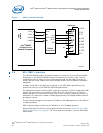
shown in Figure 3 on page 25 and Figure 4 on page 26. During byte mode accesses,
the remaining data signals not being used EX_DATA[31:8], are driven by the processor
to an unpredictable state on WRITE cycles and tri-stated during READ cycles.
When booting an 8-bit flash device, the expansion bus must be configured during reset
to the 8-bit mode (see Configuration Register 0). To accomplish this, boot-strapping is
required in certain address pins of the Expansion bus. For example, as in this case
when booting of an 8-bit flash device, bit 0 and 7 of Configuration Register 0 must be
set as follows:
Bit 0 = 1. By default this bit is set high when coming off reset or any time reset is
asserted.
Bit 7 = 0. This can be done by placing an external 4.7-KΩ pull-down resistor to pin
EX_ADDR[7].
If it is required to change access mode, after the system has booted, and during
normal operation; the Timing and Control Register for Chip Select must be configured
to perform the desired mode access. For a complete description on accomplishing this
refer to the “Expansion Bus” chapter in the Intel
®
IXP45X and Intel
®
IXP46X Product
Line of Network Processors Developer’s Manual.
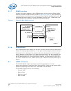
3.3.4 16-Bit Device Interface
The IXP45X/IXP46X network processors support 16-bit wide data bus devices (16-bit
word mode). For Intel interface cycles, the data lines and control signals can be
connected as shown in Figure 3 on page 25 and Figure 4 on page 26. During word
mode accesses, the remaining data signals not being used EX_DATA[31:16], are driven
by the processor to an unpredictable state on WRITE cycles and tri-stated during READ
cycles.
When booting a 16-bit flash device, the expansion bus must be configured during reset
to the 16-bit mode (see Configuration Register 0). To accomplish this, boot-strapping is
required in certain address pins of the Expansion bus.
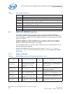
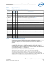
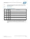
EX_ADDR[2] PCI_ARB
Enables the PCI Controller Arbiter
0 = PCI arbiter disabled
1 = PCI arbiter enabled
EX_ADDR[1] PCI_HOST
Configures the PCI Controller as PCI Bus Host
0 = PCI as non-host
1 = PCI as host
EX_ADDR[0] 8/16_FLASH
Specifies the data bus width of the FLASH memory device found on Chip Select 0.
The data bus is based upon bits 0 and 7 of Configuration Register 0.
32_FLASH 8/16_FLASH Data bus size
B7 . B0
-------------------------------------------------------------------------------------
0 . . 0 16-bit
0 . . 1 8-bit
1 . . 0 (Reserved)
1 . . 1 32-bit
Table 6. Boot/Reset Strapping Configuration (Sheet 2 of 2)
Name Function Description