CBI/CGI Technical Reference
Chassis Plans A-1
Appendix A BIOS Messages
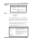
BIOS BEEP CODES Errors may occur during the POST (Power-On Self Test) routines which are performed
each time the system is powered on.
Non-fatal errors are those which, in most cases, allow the system to continue the bootup
process. The error message normally appears on the screen. See BIOS Error Messages
later in this appendix for descriptions of these messages.
Fatal errors are those which will not allow the system to continue the bootup procedure.
These fatal errors are usually communicated through a series of audible beeps. Each
error message has its own specific beep code, defined by the number of beeps following
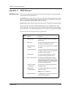
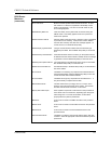
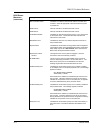
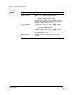
the error detection. The following table lists the errors which are communicated audibly.
All errors listed, with the exception of #8, are fatal errors.
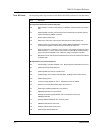
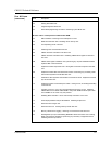
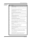
Beep
Count Message Description
1
2
3
4
5
6
7
8
9
Refresh Failure
Parity Error
Base 64KB Memory
Failure
Timer Not Operational
Processor Error
8042 - Gate A20 Failure
Processor Exception
Interrupt Error
Display Memory
Read/Write Error
ROM Checksum Error
The memory refresh circuitry of the processor
board is faulty.
A parity error was detected in the base memory
(the first block of 64KB) of the system.
A memory failure occurred within the first 64KB
of memory.
A memory failure occurred within the first 64KB
of memory, or Timer #1 on the processor board
has failed to function properly.
The CPU (Central Processing Unit) on the
processor board has generated an error.
The keyboard controller (8042) contains the
Gate A20 switch which allows the processor to
operate in protected mode. This error message
means that the BIOS is not able to switch the
processor into protected mode.
The processor on the SBC has generated an
exception interrupt.
The system video adapter is either missing or
its memory is faulty.
NOTE: This is not a fatal error.
The ROM checksum value does not match the
value encoded in the BIOS.


