Specifications CBI/CGI Technical Reference
Chassis Plans1-20
CONNECTORS
(
CONTINUED)
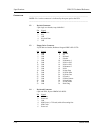
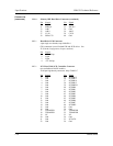
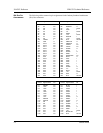
P11A - Primary IDE Hard Drive Connector (continued)
Pin
29
31
33
35
37
39
Signal
DACK 1
MIRQ 0
Add 1
Add 0
CS 1S
IDEACTS
Pin
30
32
34
36
38
40
Signal
Gnd
IOCS16
Gnd
Add 2
CS 3S
Gnd
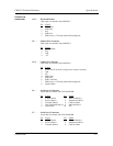
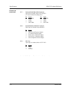
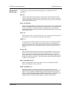
P12 - Hard Drive LED Connector
4 pin single row header, Amp #640456-4
(This connector is used for both IDE and SCSI drives. See
JU19 in the Configuration Jumpers section.)
Pin
1
2
3
4
Signal
+5V Pull-up
Light
Light
+5V Pull-up
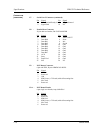
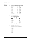
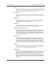
P13 - PCI Ultra Wide SCSI Controller Connector
(not available on BASIC models)
50/68 pin high density connector, Amp #749069-7
Pin
1
2
3
4
5
6
7
8
9
10
11
12
13
14
15
16
17
18
19
20
21
22
Signal
Gnd
Gnd
Gnd
Gnd
Gnd
Gnd
Gnd
Gnd
Gnd
Gnd
Gnd
Gnd
Gnd
Gnd
Gnd
Gnd
TERMPWR
TERMPWR
NC
Gnd
Gnd
Gnd
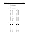
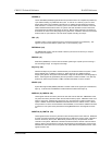
Pin
35
36
37
38
39
40
41
42
43
44
45
46
47
48
49
50
51
52
53
54
55
56
Signal
SCZDB12
SCZDB13
SCZDB14
SCZDB15
SCZDBPH
SCZDB0
SCZDB1
SCZDB2
SCZDB3
SCZDB4
SCZDB5
SCZDB6
SCZDB7
SCZDBP
Gnd
Gnd
TERMPWR
TERMPWR
NC
Gnd
SCZATN
Gnd


