


Replace the Fan Tr
ay
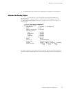
Tool or part Components
Phillips (+) screwdrivers, numbers
1and2
Fan tray
FEB
PIC
Power supply (AC or DC)
Routing Engine
Rubber safety cap Fiber-optic PIC or PIC cable
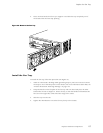
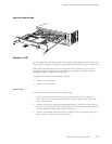
Replace the Fan Tray
The fan tray installs into the rear of the chassis, as shown in Figure 3. It houses four fans and
weighs approximately 4 lb (1.8 kg). To replace the fan tray, perform the following procedures:
• Remove the Fan Tray on page 82
• Install the Fan Tray on page 83
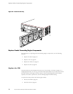
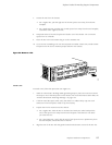
Remove the Fan Tray
To remove the fan tray, follow this procedure (see Figure 26):
Do not remove the fan tray for more than a about one minute while the
router is ope
rating. The fans are the sole source of cooling, and the router
can overheat when they are absent.
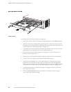
1. Attach an electrostatic discharge (ESD) grounding strap to your bare wrist and connect
the strap to one of the ESD points on the chassis. For more information about ESD, see
“Prevent Electrostatic Discharge Damage” on page 134.
2. Loosen the thumbscrews above and below the handle on the fan tray faceplate, using a
Phillips screwdriver if necessary.
3. Grasp the handle on the faceplate and slide the tray about halfway out of the chassis.
To avoid injury, keep tools and your fingers away from the fans as you slide
the fan tray out of the chassis. The fans might still b e spinning.
82 M5 and M10 Internet Routers Hardware Guide