


Replace Routing E
ngine Components
4. Attach an electrostatic discharge (ESD) grounding strap to your bare wrist and connect
the strap to one of the ESD points on the chassis. For more information about ESD, see
“Prevent Elec
trostatic Discharge Damage” on page 134.
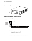
5. Using a Philli
ps screwdriver, loosen and remove the five screws that secure the Routing
Engine cover to the FEB faceplate (the cover is shown in Figure 3). Pull the cover
straight off the Routing Engine. Save the screws.
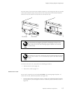
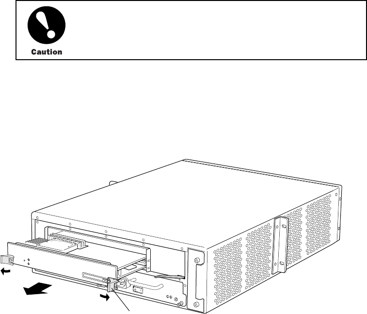
6. Using your thumbs, push and hold the red tab on each extractor clip toward the outer
edge of the un
it. Push the ends of the extractor clips outward to unseat the Routing
Engine from the chassis.
7. Grasp the extractor clips and slide the unit about halfway out of the chassis.
Slide the Routing Engine straight out of the chassis. Damage can result if it
gets lodge
d because of uneven movement.
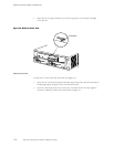
8. Place one hand under the Routing Engine to support it, slide it completely out of the
chassis, and place it on the antistatic mat or in the electrostatic bag.
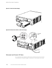
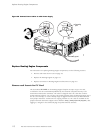
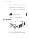
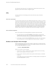
Figure 42: Remove the Routing Engine
1312
Extractor
clip
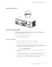
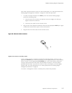
Install the Routing Engine
To install the Routing Engine, follow this procedure (see Figure 43):
1. Verify that
the p ower switch on both power supply faceplates is in the OFF (O)position.
11 6 M5 and M10 Internet Routers Hardware Guide