


Replace Power Sys
tem Components
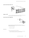
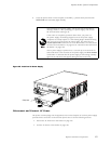
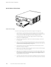
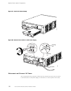
5. Press the power switch on the faceplate of one power sup ply to the ON ( | ) position.
Verify that the blue OUTPUT OK LED eventually lights steadily.
After powering off a power supply, wait at least 60 seconds before
turning it back on. After powering on a power supply, wait at least
60 seconds before turning it off.
If the router i
s c om pletely powered down when you power on
the power supply, t he Routing Engine boots as the power supply
completes its
startup sequence. If the Routing Engine finishes booting
and you need to power down the router again, first issue the CLI
request syst
em halt command. For more information, see “Disconnect
ACPowerfromtheRouter”onpage102or“DisconnectDCPowerfrom
the Router” o
n page 109.
After a power supply is powered on, it can take up to 60 seconds for
status indicators—such as LEDs on the power supply and show chassis
commands—to indicate that the p ower supp ly is functioning normally.
Ignore error indicators that appear during the first 60 seconds.
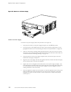
6. Press the power sw it
ch on the other power supply to the ON ( | ) position and observe the
LEDs on the power supply faceplate. They should light as desc ribed in the previous step.
IftheLEDsarenotlitintheappropriatepattern after 60 seconds, repeat the procedures
in “Install an AC Power Supply” on page 100 and the previous steps in this procedure.
When two power supplies are installed, at least one Routing Engine and one
FPC must also be installed for both power supplies to power on. In the
absence of this minimum load, only one power supply starts. (The router
powers on and operates correctly with one power supply, but without the
redundancy benefit of having a second power supply installed.)
7. On the external management device connected to the Routing Engine, monitor the
startup process to verif
y that the system has booted properly.
ReplaceanACPowerCord
To replace the power cord for an AC power supply, follow this procedure:
1. Locate a replacement po
wer cord with the type of plug appropriate for your geographical
location (see “AC Grounding and Power Cord Specifications” on page 45).
2. Attach an electrostatic discharge (ESD) grounding strap to your bare wrist and connect
the strap to one of the ESD points on the chassis. For more information about ESD, see
“Prevent Electrostat
ic Discharge Damage” on page 134.
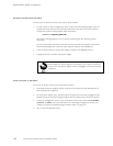
3. Press the power switc
h on the power supply faceplate to the OFF (O)position.
Replace Hardware Components
103