


Replace Routing E
ngine Components
2. Attach an electrostatic discharge (ESD) grounding strap to your bare wrist and connect
the strap to one of the ESD points on the chassis. For more information about ESD, see
“Prevent Elec
trostatic Discharge Damage” on page 134.
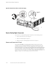
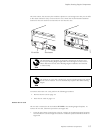
3. Verify that th
e extractor clip at each end of the Routing Engine is flipped toward the outer
edge of the unit. If necessary, use your thumbs to push and hold the red tab on each
extractor clip toward the outer edge, then push the ends of the extractor clips outward.
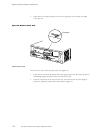
4. Place one hand under the Routing Engine to support it and grasp one of the extractor
clips on the f
aceplate with the other hand.
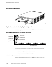
5. Align the re
ar of the Routing Engine with the guide rails inside the chassis and slide
it in comp letely.
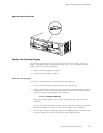
Align the Routing Engine carefully with the guide rails and push it in evenly.
Damage can
result if it gets lodged in the rails because of uneven movement.
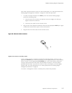
6. Press the extractor clip at each end of the Routing Engine inward to seat the unit
firmly in the chassis.
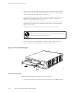
7. ReplacetheRoutingEnginecoverontheFEBfaceplate,byslidingthehooksatthe
bottom of the cov
er under the lower edge of the FEB ejector levers and aligning the
holes in the cover w ith the holes in the faceplate (the cover is shown in Figure 3). Insert
screws into the five holes in the cover and use a Phillips screwdriver to tighten them.
8. Perform the procedures in “Power On the Router” on page 67to power on the router
and verify corr
ect startup.
9. Issue the show
chassis routing-engine command described in “Maintain the Routing
Engine” on page 79 to verify correct Routing Engine functioning.
Replace Hardware Components
11 7