


Replace Power Sys
tem Components
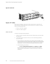
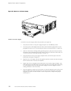
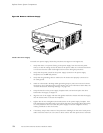
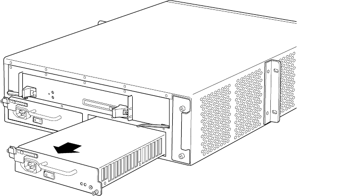
Figure 34: Remove an AC Power Supply
1317
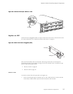
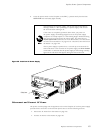
InstallanACPowerSupply
To install an AC power supply, follow this procedure (see Figure 35):
1. Verify that the switch on the power supply faceplate is in the OFF (O)position.
2. Locate the power cord shipped with the router, which should be appropriate for your
geographical location (see “AC Grounding and Power Cord Specifications” on page 45).
3. Attach an electrostatic discharge (ESD) grounding strap to your bare wrist and connect
the strap to one of the ESD points on the chassis. For more information about ESD, see
“Prevent Electrostatic Discharge Damage” on page 134.
4. Grasp the handle on the power supply faceplate with one hand and place the other
hand under the supply to support it.
5. Align the rear of the su pply with the slide gu i des inside t he chassis a nd slide the supply
into the chassis until it contacts the midplane.
6. Tighten (but do not overtighten) the thumbscrews on the p ower sup ply faceplate. Turn
both thumbscrews simultaneously and at about the same rate (turning them alternately
or at very different rates can cause the power supply to become lodged in the slot,
making it difficult to turn the screws).
7. Insert the appliance coupler end of the power cord into the a ppliance inlet on the power
supply faceplate and insert the plug into an AC p ower source receptacle. Verify that
the power cord does not block access to router components or drape where people
couldtriponit.
100 M5 and M10 Internet Routers Hardware Guide