


Overview of Troub
leshooting Resources
For information about using the CLI to troubleshoot the JUNOS Internet software, see the
appropriate JUNOS Internet software configuration guide.
LEDs
The LEDs described in the following sections indicate the basic status of hardware
components.
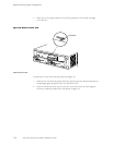
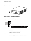
LEDs on the Craft Interface
The craft interface provides status and troubleshooting information at a glance. It is located
on the front of the chassis above the FPC card cage , as shown in Figure 1 and Figure 2. The
LEDs on th e craft interface include t wo alarm LEDs. The circular red a larm LED at the upper
left of the craft interface indicates a c ritical condition that can result in a system shutdown.
The triangular yellow alarm below it indicates a less severe condition that requires monitoring
or maintenance. Both alarms can occur simultaneously. For more information about the
alarm LEDs, see “Alarm LEDs and Lamp Test Button” on page 15. For more information
about the causes of alarms, see “Hardware and Interface Alarm Messages” on page 122.
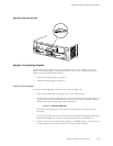
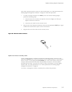
LEDs on Hardware Components
LEDs on the faceplates of the following hardware components report their status:
• PIC—Most PI
Cs have an LED labeled STATUS on their faceplate. Some PICs have
additional LEDs, often one per port. The meaning of the LED states differs for various
PICs. For more information, see the M5 and M10 Internet Routers PIC Guide.
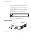
• Power supply—A blue LED labeled OUTPUT OK reports the status of the power supply.
For more information, see “Power Supply LEDs and Self-test Button” on page 19.
Hardware and Interface Alarm Messages
When the Routing Engine detects an alarm condition, it lights the red or yellow alarm LED
on the craft interface as appropriate. To view a more detailed description of the alarm cause,
issue the s
how chassis alarms CLI command:
user@host> show chassis alar m s
There are two classes of alarm messages:
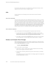
• Chassis al
arms—Indicate a problem with a chassis component such as the cooling
system or power supplies, as described in Table 17.
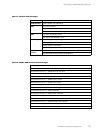
• Interfac
e alarms—Indicate a problem with a specific network interface, as described
in Table 18.
In both ta
bles, the text in the column labeled “CLI Message” appears in t he output from
the show chassis alarms command.
122 M5 and M10 Internet Routers Hardware Guide