


Maintain Packet F
orwarding Engine Components
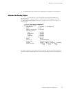
• Issue the CLI show chassis fpc pic-status command. The PIC slots in an FPC are
numbered from 0 through 3,righttoleft:
user@host> show chassis fpc pic-status
Slot 0 Online
PIC 0 4x OC-3 SO
NET, MM
PIC 1 1x CSTM1, SMIR
PIC 3 2x OC-3 ATM, MM
Slot 1 Online
PIC 0 1x OC-12 SONET, MM
PIC 1 1x OC-12 ATM, MM
PIC 2 2x OC-3 ATM,
MM
PIC 3 2x OC-3 ATM, MM
For further description of the output from the command, see the JUNOS Internet
Software Operational Mode Command Reference: Protocols, Class of Service, Chassis,
and Management
.
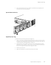
• Use the cable management system (shown in Figure 11) to support cables and prevent
cables from dis
lodgingordevelopingstresspoints.
• Place excess cable out of the way in the cable management system. Do not allow
fastened loops
of cable to dangle from the connector or cable management system,
because this stresses the cable at the fastening point. Putting fasteners on the loops
helps to maintain their shape.
• Keep the cable connections clean and free of dust and other particles, which can cause
drops in the received power level. Always inspect cables and clean them if necessary
before connec
ting an interface.
• Label both ends of PIC cab les to identify them.
The following guidelines apply specifically to fiber-optic cable:
• When you unplu
g a fiber-optic cable from a PIC, always place a rubber safety plug over
thetransceiveronthePICfaceplateandontheendofthecable.
• Anchor fiber-
optic cable to avoid s tress on the connectors. When attaching fiber to a
PIC, be sure to secure the fiber so it is not supporting its own weight as it hangs to the
floor. Never let fiber-optic cable han g free from the connector.
• Avoid bending fiber-optic cable beyond its bend radius. An arc smaller than a few
inches can damage the cable and cause problems that are difficult to diagnose.
• Frequent plugging and unplugging of fiber-optic cable into and out of optical
instruments, such as ATM o r S ONET/SDH analyzers, can cause damage to the
instrument
s that is expensive to repair. Instead, attach a short fiber extension to the
optical equipmen t. Any wear and tear due to frequent plugging and unplugging is then
absorbed by the short fiber extension, which is easy and inexpensive to replace.
• Keep fiber-optic cable connections clean. Small micro-deposits of oil and dust in the
canal of the transceiver o r cable connector could cause loss of light, reducing signal
power and po
ssibly causing intermittent problems with the optical connection.
Maintain Hardware Components
77