


Site Preparation
Checklist
the power to bring it within the allowable range; for short lengths of fiber, with fiber and
connector loss close to zero, an attenuator of 5 to 10 dB should be sufficient.
For specifications of minimum and maximum input level (receiver sensitivity and receiver
saturation) and minimum and maximum output level (average launch power) for the
SONET/SDH PIC
s supported on the M5 and M10 routers, see the M5 and M10 Internet
Routers PIC Guide.
Cable Specifications for Routing Engine Management Interfaces
For management and service operations, you connect the Routing Engine to an external
console o r management network through ports on the craft interface. For information about
the ports, se
e “Routing Engine Interface Ports and Status Indicators” on page 15.
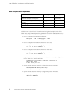
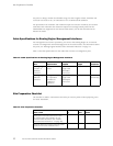
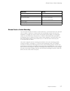
Table 13 lists the specifications for the cables that connect to management ports.
Table 13: Cable Specifications for Routing Engine Management Interfaces
Port
Cable
Specification
Cable/Wire
Supplied
Maximum
Length
Router
Receptacle
Routing Engine
console or
auxiliary
interface
RS-232 (EIA-232)
serial
One 6-ft (1.83-m)
length with
DB-9/DB-9
connectors
6 ft (1.83 m) DB-9 male
Routing Engine
Ethernet
interface
Category 5
cable
or equivalent
suitable f
or
100BaseT
operation
One 15-ft (
4.57-m)
length with
RJ-45/RJ-
45
connectors
328 ft (100
m)
RJ-45
autosensing
Site Preparation Checklist
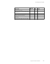
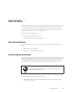
The checkl
ist in Table 14 summarizes the tasks you need to perform when preparing a site
forrouterinstallation.
Table 14: Site Preparation Checklist
Item or Task
Performed
By Date Notes
Verify t
hat environmental factors such
as temperature and humidity do not
exceed r
outer tolerances (see “Router
Environmental Tolerances” on page 40).
Measure distance between external power
sources and router installation site.
52 M5 and M10 Internet Routers Hardware Guide