


Appendix C
Cable Connec
tor Pinouts
This chapter describes the pinouts for the following cab le connectors:
• RJ-45 Connector Pinouts for the Routing Engine MGMT Port on page 171
• DB-9 Connect
or Pinouts for the Routing Engine AUX/MODEM and CONSOLE Ports
on page 171
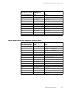
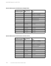
• RJ-48 Cable Pinouts for E1 and T1 PICs on page 172
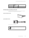
• RJ-21 Cable Pinouts for Fast Et hernet 12-Port PIC on page 175
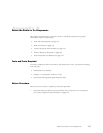
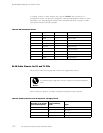
RJ-45 Connector Pinouts for the Routing Engine MGMT Port
The port on the craft interface labeled MGMT is an autosensing 10/100-Mbps Ethern et
RJ-45 receptacle that accepts an Ethernet cable for connecting the Routing Engine to a
management LAN (or other device that supports out-of-band management). For more
information, see “Routing Engine Interface Ports and Status Indicators” on page 15. Table
19 describes the RJ-45 connector pinout.
Table 19: RJ
-45 Connector Pinout
Pin Signal
1TX+
2TX-
3
RX+
4
Termination network
5
Termination network
6
RX-
7
Termination network
8
Termination network
DB-9 Conn
ector Pinouts for the Routing Engine AUX/MODEM and CONSOLE Ports
The ports on the craft interface labeled AUX/MODEM and CONSOLE are DB-9 receptacles
that acce
pt RS-232 (EIA-232) cable. The AUX/MODEM port connects the Routing Engine
Cable Connector Pinouts
171