


Fan T ray
Description Specificatio
n
Input DC current rating 13.5 A @ –48 V
Output voltages
+1.5 V, +2.5 V, +3.3 V, +5.0 V, +12 V, +12 V
The DC power supplies are marked –48 VDC. This is the nominal voltage
associated with the battery circuit. Any higher voltages are to be associated
only with float voltages for t he charging function.
Power Supply LEDs and Self-test Button
Table 7 describes the LED on both AC and DC power supplies.
Table 7: States for Power Supply LED
Label Color State Description
On steadily Power supply is functioning normally, input is
occurring, outputs are within range, and the
temperature is w ithin range.
OUTPUT
OK
Blue
Blinking Power supply has failed.
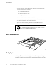
The self-test button on the power supply faceplate initiates a self-test sequence. Do not press
this button; it is for use by qualified service personnel only.
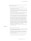
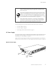
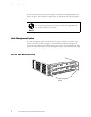
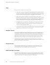
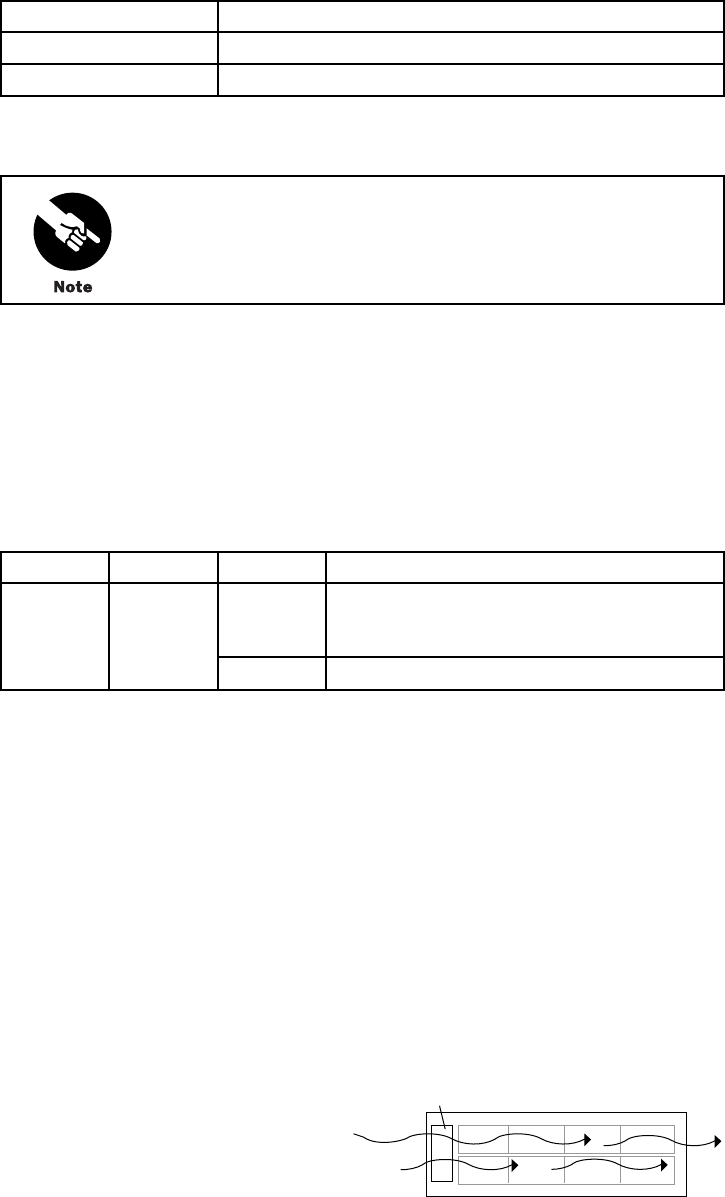
Fan T ray
The router cooling system consists of a fan tray that i nstalls into the chassis from the rear, as
shown in Figure 3. It houses four fans, which draw room air into the chassis to keep the
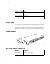
internal temperature below a maximum acceptable level. The air flows side-to-side in the
chassis, as shown in Figure 10.
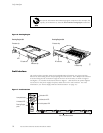
Figure 10: Airflow through the Chassis
1305
Front of chassisFan tray
Hardware Component Overview 19