


Router Environme
ntal Tolerances
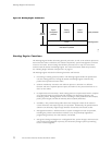
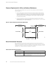
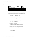
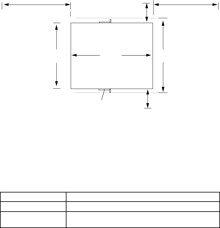
Clearance Requirements for Airflow and Hardware Maintenance
When planning
the installation site, you need to allow sufficient clearance around the
rack (see Figure 17):
• For the coolin
g system to function properly, the airflow around the chassis must be
unrestricted. Allowing at least 6 in. (15.2 cm) of clearance between each side of the
chassis and adjacent racks or equipment is recommended, particularly for routers in
which air flo
ws from side to side through the chassis. Figure 10 depicts the airflow
in the M5 and M10 routers.
• For service p
ersonnel to remove and install hardware com ponents, there must be
adequate space at the front and back of the router. Allow at least 24 in. (61 cm) in front
of the router and 19 in. (48.3 cm) behind it.
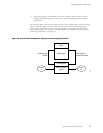
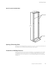
Figure 17: Chassis Dimensions and Clearance Requirements
Rear of chassisFront of chassis
Mounting ear
17.5"
44.5 cm
24"
(61 cm)
Clearance required
for maintenance
Clearance required
for maintenance
1303
19" (48.3 cm)24" (61 cm)
19"
(48.3 cm)
6" (15.2 cm)
for airflow
6" (15.2 cm)
for airflow
Router Environmental Tolerances
Table 8 specifies the environmental conditions required for normal router operation. In
addition, the site should be as dust-free as possible. Dust can clog air intake vents, reducing
cooling system efficiency. Check the vents frequently, cleaning them as necessary. For more
information, see “Maintain Hardware Components” on page 75.
Table 8: Router Environmental Tolerances
Description Tolerance
Altitude No performance degradation to 10,000 ft (3048 m)
Relati
ve humidity
Normal
operation ensured in relative humidity range o f 5% to
90%, noncondensing
40 M5 and M10 Internet Routers Hardware Guide